9
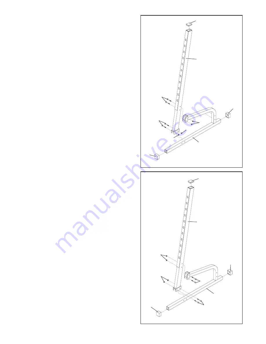
11. Press a 51.8mm x 76.2mm Inner Cap (24) into the
top end of the remaining Upright (1).
Press an Outer Cap (25) onto each end of the
remaining Base (2).
Place the bracket on the lower end of the Upright (1)
over the indicated holes in the Base (2).
Note: During the following steps, make sure the
M10 x 68mm Bolts (33) are inserted from the
direction shown in the drawing.
Attach the Upright (1) to the lower arm of the Base
(2) with two M10 x 68mm Bolts (33) and two M10
Nylon Locknuts (11).
Do not tighten the Nylon
Locknuts yet.
Attach the Upright (1) to the bracket on the upper arm
of the Base (2) with two M10 x 68mm Bolts (33) and
two M10 Nylon Locknuts (11).
Do not tighten the
Nylon Locknuts yet.
Note: Set the upright assembly aside so it cannot
fall over. In step 13 this upright assembly will be
mounted on the left side of the bench.
11
10. Press a 51.8mm x 76.2mm Inner Cap (24) into the
top end of one Upright (1).
Press an Outer Cap (25) onto each end of one Base
(2).
Place the bracket on the lower end of the Upright (1)
over the indicated holes in the Base (2).
Note: During the following steps, make sure the
M10 x 68mm Bolts (33) are inserted from the
direction shown in the drawing.
Attach the Upright (1) to the lower arm of the Base
(2) with two M10 x 68mm Bolts (33) and two M10
Nylon Locknuts (11).
Do not tighten the Nylon
Locknuts yet.
Attach the Upright (1) to the bracket on the upper arm
of the Base (2) with two M10 x 68mm Bolts (33) and
two M10 Nylon Locknuts (11).
Do not tighten the
Nylon Locknuts yet.
Note: Set the upright assembly aside so it cannot
fall over. In step 13 this upright assembly will be
mounted on the right side of the bench. See the
drawing on page 4 to determine what is the right
and the left side.
10
33
25
25
1
11
2
33
1
24
33
33
11
11
11
2
24
11
25
25


