background image

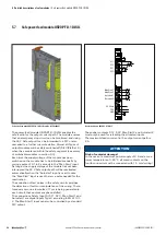
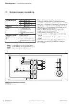
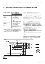
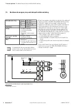
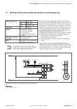
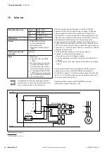
5 Detailed descriptions of safe modules 

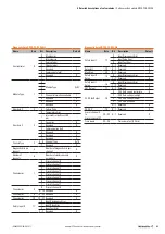
| Safe power-feed module UR20-PF-O-2DI-DELAY-SIL

68

1484600000/04/06.2017

u-remote IP20 modules for functional safety manual 

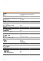
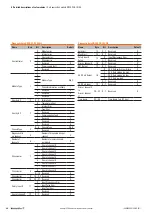
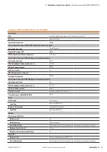
Technical data UR20-PF-O-2DI-DELAY-SIL Order No. 1335040000)

Auxiliary outputs

3 x 2

Output current

Max. 10 

mA (only to support the inputs dedicated inputs)

Diagnosis
Module diagnosis

yes

Individual channel diagnosis

yes

Supply
Supply voltage

24 V DC +20 %/-15 % 

External pre-fusing

Mandatory: super fast, max. 8 A

Reverse battery protection

yes

Current consumption from system current path I

SYS

8 mA

Current consumption from input current path I

IN

45

 mA 

General data
Weight (operational status)

84 g

Additional general data, see Section 5.1

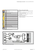
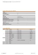
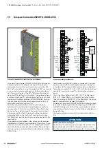
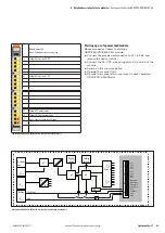
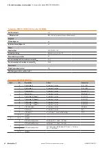
Prozess data UR20-PF-O-2DI-DELAY-SIL

Byte

Bit

Description

Status

Connection

0

0

Safety Input 0

0 - inactive, 1 - active

S 11 ... S 22

1

Safety Input 1

0 - inactive, 1 - active

S 31 ... S 42

2

Automatic start

0 - inactive, 1 - active

Autostart 1/2

3

Manual start

0 - inactive, 1 - active

Man Start 1/2

4

Safety Input 0,

 Channel 1

0 - inactive, 1 - active

S 11/S 12

5

Safety Input 0, 

Channel 2

0 - inactive, 1 - active

S 21/S 22

6

Safety Input 1,

 Channel 1

0 - inactive, 1 - active

S 31/S 32

7

Safety Input 1

, Channel 2

0 - inactive, 1 - active

S 41/S 42

1

0

24 V Safe output

0 - inactive, 1 - active

24 V Safe

1

SS1 output

0 - inactive, 1 - active

SS 1

2

24 V feed-in

0 - no feed-in, 1 - power feed-in pending

24 V

3 ... 7

reserved


2

0 ... 7

reserved


3

0

DIP-Switch 

configuration

Safety input 0

: 0 - Pulse,1 - No Pulse

1

DIP-Switch 

configuration

Safety input 1: 

0 - Pulse,1 - No Pulse

2

DIP-Switch 

configuration

24 V Safe output: 00 - No delay, 01 - Delay 1 s, 10 - Delay 

30 s, 11 - Delay 60 s

3

4 ... 7

reserved


Summary of Contents for UR20-4DI-4DO-PN-FSOE

Page 1: ...Remote I O system u remote IP20 modules for functional safety Manual Original Letʼs connect ...

Page 2: ... safe I O modules 73 7 2 Dual channel emergency stop monitoring 76 7 3 Dual channel light curtain monitoring AOPD type 4 and emergency stop monitoring 77 7 4 Dual channel emergency stop and cable pull switch monitoring 78 7 5 Dual channel safety door monitoring with automatic reset and emergency stop 79 7 6 Safety mat 80 7 7 Dual channel two hand monitoring with automatic start 81 7 8 Dual channel...

Page 3: ... the instructions given in this manual ATTENTION Material damage Notes with the signal word Attention warn you of hazards which may result in material damage Text next to this arrow are notes which are not relevant to safety but provide important information about proper and effective work procedures The situation dependent safety notices may contain the fol lowing warning symbols Symbol Meaning W...

Page 4: ...1 About this documentation Complete documentation 4 1484600000 04 06 2017 u remote IP20 modules for functional safety manual ...

Page 5: ... operated in lockable housings cabinets or electri cal operations rooms Only trained and authorised personnel may access the equipment For applications requiring functional safety the surrounding housing must meet at least IP54 The standards and guidelines applicable for the assembly of switch cabinets and the arrangement of data and supply lines must be complied with Fusing If safe I O modules or...

Page 6: ...ontact the temperature specification of the selected cable shall be in compliance with the actual measured temperature values A visual inspection of the u remote station is to be per formed once per year 2 4 Notes on functional safety Safety Integrity Level SIL The safety requirements necessary for the safety functions of an application are determined in a risk analysis Here the probability of the...

Page 7: ... signal generators that are suited for the respective required safety level may be used Positively opening control switches must be used in accordance with IEC 60947 5 1 designated with this symbol Only use components that have been proven in operation Depending on the established risk level switches e g for position monitoring may have to have a redundant design Depending on the required safety l...

Page 8: ...8 1484600000 04 06 2017 u remote IP20 modules for functional safety manual ...

Page 9: ...architectures 1oo2 can be realised with the safe inputs and outputs also mixed operation is possible In case of failure of the safety control the modules change into the safe status X1 X2 DI M DI DO DI DO DO DO DO FS FS AO DO Safety control Example set up of safe I O modules FS in a u remote station 1 Safety over EtherCAT is a registered trademark and patented technology licensed by Beckhoff Autom...

Page 10: ...ty control Unrecoverable fault State 1 Waiting for parameter State 4 Requesting acknowledgement by safety control State 3 Fault Transition diagramm for safe I O modules 3 3 Current voltage characteristics of the fail safe digital inputs 0 0 2 20 10 4 6 8 12 14 16 18 3 2 1 4 V mA Inputs off Inputs on Current voltage characteristic for P switching inputs 0 0 2 20 10 4 6 8 12 14 16 18 3 2 1 4 V mA In...

Page 11: ...0 0 0 0 0 0 0 1 0 0 0 0 0 0 0 0 0 0 1 0 0 0 0 0 0 0 0 0 0 1 0 0 0 0 0 0 0 0 0 0 1 0 0 0 0 0 0 0 0 0 0 1 0 0 0 0 0 0 0 0 0 0 1 0 0 0 0 0 0 0 0 0 0 1 0 0 0 0 0 0 0 0 0 0 1 0 0 0 0 0 0 0 0 0 0 1 0 0 0 0 0 0 0 0 0 0 1 0 0 0 0 0 0 0 0 0 0 1 0 0 0 0 0 0 0 0 0 0 1 0 0 0 0 0 0 0 0 0 0 0 1234 0 1 0 0 1 1 0 1 0 0 1 0 Example Address 1234 is represented by setting 0000010011010010 Please use e g a ball pen t...

Page 12: ...dules only Example 3 Dual channel first channel N switching The outputs correspond with the type D source 1 2 3 4 1 2 3 4 1 2 3 4 DO PN DO P DO PN 24 V DC DO P DO PN DO P 1 2 3 External dual channel circuitry of the outputs Test pulse class Parameterisable per test pulse duration Test pulse duration Depending on the parameterisation 0 5 10 ms Test pulse intervall 200 ms Rated current 0 5 A as per ...

Page 13: ...typ Antivalent circuits are possible with V2 modules only 1 2 3 4 DI X PN AUX O X AUX O Y DI Y P Connecting example with antivalent input circuit V2 only For the operation with test pulses the V2 modules can be installed either with three or with four wires 1 2 3 4 DI X AUX O X AUX O Y DI Y Operation with own test pulses 4 wire installation 1 2 3 4 DI X AUX O X AUX O Y DI Y Operation with own test...

Page 14: ...t the module shall be used as type A source with disabled test pulses the DI X input must be parameterised N switching 1 2 3 4 DI X N AUX O X AUX O Y DI Y P Operation without own test pulses type A source with N switching DI X 3 8 Processing time The response time for each input or output of a safe I O module is 10 ms The processing time of a signal within the safety chain can be calculated as fol...

Page 15: ... short circuits Three types of safe power feed modules are available in the u remote system UR20 PF O 1DI SIL one safe input UR20 PF O 2DI SIL two safe inputs UR20 PF O 2DI DELAY SIL two safe inputs delayed switching off possible Thereby the following safety functions can be implemented Up to two dual channel safety circuits AND linked e g for emergency stop switch safety door contacts and safety ...

Page 16: ...ioned within a safety segment For detailed planning please also observe the notes in the section Configuration DI DI DO DI DO DO DO DO PF O SIL PF O AO DO FB UOUT 24 V Safe UOUT 24 V UIN 24 V 24 V 24 V 24 V 1 Example set up of a safety segment 1 with PF O xDI SIL To switch the 24 V Safe voltage back on either an automatic or a manual start can be selected Automatic start the safe output current pa...

Page 17: ...n Safety circuit inactive3 Safety circuit active1 Autostart mode Safety circuit inactive3 delay State 1 Idle 24 VSafe off SS1 off State 3 Wait for power off 24 VSafe on SS1 off 1 Both channels of a safety circuit must get active within a discrepancy time of 0 5s max 2 The 24 V Safe output remains on until delay time is expired 3 At least one channel of the safety circuit Transition diagramm of saf...

Page 18: ... load output is not designed for either inductive or capacitive loads The feed in of the PF O xDI SIL module must be safeguarded with a 8 A super fast fuse A SELV PELV power supply must be used The safely shut off systems applications must get their power exclusively from the safe feed in module PF O xDI SIL Likewise it must not be possible to feed external energy into the safety segment elsewhere...

Page 19: ... S41 S22 S42 24 V DC Safety relay Sensor Exemplary operation with test pulses The safe power feed module UR20 PF O 2DI DELAY SIL might also be operated without test pulses This is mandato ry whenever an external device gernerating own test pulses is connected When using switching devices generating own test pulses please regard that low level with a duration of more than 2 ms will be detected as a...

Page 20: ...20 1484600000 04 06 2017 u remote IP20 modules for functional safety manual ...

Page 21: ...port 700 hPa altitude 3000 m as per IEC 61131 2 Vibration resistance 5 Hz f 8 4 Hz 3 5 mm amplitude as per IEC 60068 2 6 8 4 Hz f 150 Hz 1 g acceleration as per IEC 60068 2 6 Shock resistance 15 g for 11 ms half sinewave as per IEC 60068 2 27 Potential isolation Test voltage Max 28 8 V within a channel 500 V DC field system Pollution severity level 2 Overvoltage category II Approvals and Standards...

Page 22: ...UR20 PF O 1DI SIL 4 47 5 1 1335040000 UR20 PF O 2DI DELAY SIL 4 47 5 1 1335050000 UR20 PF O 2DI SIL 4 47 5 1 1335060000 UR20 4DI 4DO PN FSPS 4 23 47 6 6 1335070000 UR20 8DI PN FSPS 4 23 47 6 6 2464570000 UR20 4DI 4DO PN FSPS V2 4 27 47 6 6 2464590000 UR20 8DI PN FSPS V2 4 32 47 6 6 Max data in byte 260 4362 1408 512 512 UR20 FBC EC 1334910000 UR20 FBC EC 256 4096 3328 1024 1024 1335030000 UR20 PF ...

Page 23: ...040000 UR20 PF O 2DI DELAY SIL 4 47 4 1335050000 UR20 PF O 2DI SIL 4 47 4 Max data in byte 264 400 47 496 504 496 504 UR20 FBC CAN 1334890000 UR20 FBC CAN 47 1335030000 UR20 PF O 1DI SIL 2 47 4 1335040000 UR20 PF O 2DI DELAY SIL 2 47 4 1335050000 UR20 PF O 2DI SIL 2 47 4 Max data in byte 128 3055 256 256 UR20 FBC MOD TCP Order No Module Process data Input Output Bytes Bytes 1335030000 UR20 PF O 1D...

Page 24: ...ts as well as the out puts with power from the output current path IOUT A test pulse check of the inputs can be parameterised as a cross circuit detection between input singal and supply volt age between different input signals or other signals Thus an input gets active only when the signal of the dedicated auxil iary output is pending The test pulses must be disabled if a safety relay with OSSD o...

Page 25: ... active 2 1 Yellow Input 2 active 2 3 Red Error sensor supply or input 2 or input 3 2 4 Yellow Input 3 active 3 1 Yellow Output 0 active 3 2 Red Error output 0 3 3 Yellow Output 1 active 3 4 Red Error output 1 4 1 Yellow Output 2 active 4 2 Red Error output 2 4 3 Yellow Output 3 active 4 4 Red Error output 3 LED indicators UR20 4DI 4DO PN FSOE UR20 4DI 4DO PN FSOE V2 error messages see Chapter 7 S...

Page 26: ...afety level inputs Single channel circuit 1oo1 Dual channel circuit 1oo2 SILCL 2 SILCL 3 Achievable safety level outputs SILCL 3 PFH Probability of Failure per hour in 1 h inputs Single channel circuit 1oo1 Dual channel circuit 1oo2 10 8 2 94 10 9 PFH Probability of Failure per hour in 1 h outputs 5 56 10 9 Fault reaction time Single channel circuit 1oo1 5 s Safety related data according to EN 615...

Page 27: ...osis yes 1 Minimum rate of change in transition range 1 V s Deviating from EN 61131 2 the following applies for PN inputs in P switching mode The input will be read inactive if the input voltage considerably exceeds the module supply voltage Outputs Number 4 two of which are parameterisable P or N switching Type of load Ohmic inductive filament lamp load Response time 10 ms Output current per chan...

Page 28: ...10 ms 2 100 ms 3 1 ms 2 3 Test pulse disabled 0 enabled 1 disabled 2 Input polarity P switching 0 N switching 1 P switching 2 3 Input dual channel mode inputs 2 3 single channel 0 dual channel 1 single channel 2 3 Discrepancy time 5 ms 0 50 ms 1 2 s 2 30 s 3 5 ms 4 5 Output test pulse duration output 0 1 0 5 ms 0 1 ms 1 3 ms 2 10 ms 3 0 5 ms 4 Output polarity P switching 0 N switching 1 P switchin...

Page 29: ...tput polarity P switching 0 N switching 1 P switching 6 7 Output dual channel mode outputs 2 3 single channel 0 dual channel 1 single channel 1 Please regard the notes for parameter settings Notes for parameter settings The module independently performs a plausibility test for the relevant pair of inputs or outputs if the dual channel mode is parameterised On this it will be checked if both inputs...

Page 30: ... V2 Name Byte Bit Description Default Channel 11 error 11 0 Input 0 Short circuit 0 1 Input 0 Cross connection 0 2 Input 0 Discrepancy error 0 3 Input 0 Other error 0 4 7 Reserved 0 Channel 12 error 12 0 Input 1 Short circuit 0 1 Input 1 Cross connection 0 2 Input 1 Discrepancy error 0 3 Input 1 Other error 0 4 7 Reserved 0 Channel 13 error 13 0 Input 2 Short circuit 0 1 Input 2 Cross connection 0...

Page 31: ...DI 4DO PN FSOE UR20 4DI 4DO PN FSOE V2 Byte Bit Description IB0 IX0 0 DI0 IX0 1 DI1 IX0 2 DI2 IX0 3 DI3 IX0 4 Status DO0 UR20 4DI 4DO PN FSOE V2 only IX0 5 Status DO1 UR20 4DI 4DO PN FSOE V2 only IX0 6 Status DO2 UR20 4DI 4DO PN FSOE V2 only IX0 7 Status DO3 UR20 4DI 4DO PN FSOE V2 only Process data outputs UR20 4DI 4DO PN FSOE UR20 4DI 4DO PN FSOE V2 Byte Bit Description QB0 QX0 0 DO0 QX0 1 DO1 Q...

Page 32: ...th IIN A test pulse check of the inputs can be parameterised as a cross circuit detection between input singal and supply volt age between different input signals or other signals Thus an input gets active only when the signal of the dedicated auxil iary output is pending The test pulses must be disabled if a safety relay with OSSD outputs generating own test pulses is connected 1 2 3 4 2 1 3 4 1 ...

Page 33: ...1 active 2 1 Yellow Input 2 active 2 3 Red Error sensor supply or input 2 or input 3 2 4 Yellow Input 3 active 3 1 Yellow Input 4 active 3 3 Red Error sensor supply or input 4 or input 5 3 4 Yellow Input 5 active 4 1 Yellow Input 6 active 4 3 Red Error sensor supply or input 6 or input 7 4 4 Yellow Input 7 active LED indicators UR20 8DI PN FSOE UR20 8DI PN FSOE V2 error messages see Chapter 7 DI 0...

Page 34: ... s Safety related data as per EN 61508 Regard the entire safety chain Achievable safety level Single channel circuit 1oo1 Dual channel circuit 1oo2 SIL 2 SIL 3 PFH Probability of Failure per hour in 1 h Single channel circuit 1oo1 Dual channel circuit 1oo2 10 8 2 17 10 10 PFD Probability of Failure per Demand Single channel circuit 1oo1 Dual channel circuit 1oo2 8 77 10 4 1 85 10 5 HFT Hardware Fa...

Page 35: ...t delay 1 ms 0 3 ms 1 10 ms 2 100 ms 3 1 ms 0 1 Test pulse disabled 0 enabled 1 disabled 0 Input polarity P switching 0 N switching 1 P switching 0 1 Input dual channel mode inputs 0 1 single channel 0 dual channel 1 single channel 0 1 Discrepancy time 5 ms 0 50 ms 1 2 s 2 30 s 3 5 ms 2 3 Input delay 1 ms 0 3 ms 1 10 ms 2 100 ms 3 1 ms 2 3 Test pulse disabled 0 enabled 1 disabled 2 Input polarity ...

Page 36: ...rnal 1 from AUX5 3 internal 4 5 Input dual channel mode inputs 4 5 single channel 0 dual channel equivalent 1 dual channel antivalent 2 single channel 4 5 Discrepancy time 5 30 000 ms 500 ms 6 Input delay 1 ms 0 3 ms 1 10 ms 2 100 ms 3 1 ms 6 Test pulse internal 0 external 1 from AUX6 2 from AUX7 3 internal 6 Input polarity P switching 0 N switching 1 P switching 7 Input delay 1 ms 0 3 ms 1 10 ms ...

Page 37: ...Bit Description Default Channel 11 error 11 0 Input 0 Short circuit 0 1 Input 0 Cross connection 0 2 Input 0 Discrepancy error 0 3 Input 0 Other error 0 4 7 Reserved 0 Channel 12 error 12 0 Input 1 Short circuit 0 1 Input 1 Cross connection 0 2 Input 1 Discrepancy error 0 3 Input 1 Other error 0 4 7 Reserved 0 Channel 13 error 13 0 Input 2 Short circuit 0 1 Input 2 Cross connection 0 2 Input 2 Dis...

Page 38: ...DI PN FSOE UR20 8DI PN FSOE V2 38 1484600000 04 06 2017 u remote IP20 modules for functional safety manual Process data inputs UR20 8DI PN FSOE UR20 8DI PN FSOE V2 Byte Bit Description IB0 IX0 0 DI0 IX0 1 DI1 IX0 2 DI2 IX0 3 DI3 IX0 4 DI4 IX0 5 DI5 IX0 6 DI6 IX0 7 DI7 ...

Page 39: ...atus LED is assigned to each channel The module electronics supply the inputs as well as the out puts with power from the output current path IOUT A test pulse check of the inputs can be parameterised as a cross circuit detection between input singal and supply volt age between different input signals or other signals Thus an input gets active only when the signal of the dedicated aux iliary outpu...

Page 40: ... active 2 1 Yellow Input 2 active 2 3 Red Error sensor supply or input 2 or input 3 2 4 Yellow Input 3 active 3 1 Yellow Output 0 active 3 2 Red Error output 0 3 3 Yellow Output 1 active 3 4 Red Error output 1 4 1 Yellow Output 2 active 4 2 Red Error output 2 4 3 Yellow Output 3 active 4 4 Red Error output 3 LED indicators UR20 4DI 4DO PN FSPS UR20 4DI 4DO PN FSPS V2 error messages see Chapter 7 S...

Page 41: ...y chain Achievable safety level inputs and outputs Single channel circuit 1oo1 Dual channel circuit 1oo2 SILCL 2 SILCL 3 Achievable safety level outputs SILCL 3 PFH Probability of Failure per hour in 1 h inputs Single channel circuit 1oo1 Dual channel circuit 1oo2 10 8 2 94 10 9 PFH Probability of Failure per hour in 1 h outputs 5 56 10 9 Fault reaction time Single channel circuit 1oo1 5 s Safety ...

Page 42: ... 1 Minimum rate of change in transition range 1 V s Deviating from EN 61131 2 the following applies for PN inputs in P switching mode The input will be read inactive if the input voltage considerably exceeds the module supply voltage Outputs Number 4 two of which are parameterisable P or N switching Type of load Ohmic inductive filament lamp load Response time 10 ms Output current per channel 0 00...

Page 43: ...ty P switching 0 N switching 1 P switching 2 3 Input dual channel mode inputs 2 3 single channel 0 dual channel 1 single channel 2 3 Discrepancy time 5 ms 0 50 ms 1 2 s 2 30 s 3 5 ms 4 5 Output test pulse duration output 0 1 0 5 ms 0 1 ms 1 3 ms 2 10 ms 3 0 5 ms 4 Output polarity P switching 0 N switching 1 P switching 4 5 Output dual channel mode outputs 0 1 single channel 0 dual channel 1 single...

Page 44: ... outputs 2 3 single channel 0 dual channel 1 single channel 1 Please regard the notes for parameter settings Notes for parameter settings The module independently performs a plausibility test for the relevant pair of inputs or outputs if the dual channel mode is parameterised On this it will be checked if both inputs or outputs become active or inactive simultane ously within the discrepancy time ...

Page 45: ... V2 Name Byte Bit Description Default Channel 11 error 11 0 Input 0 Short circuit 0 1 Input 0 Cross connection 0 2 Input 0 Discrepancy error 0 3 Input 0 Other error 0 4 7 Reserved 0 Channel 12 error 12 0 Input 1 Short circuit 0 1 Input 1 Cross connection 0 2 Input 1 Discrepancy error 0 3 Input 1 Other error 0 4 7 Reserved 0 Channel 13 error 13 0 Input 2 Short circuit 0 1 Input 2 Cross connection 0...

Page 46: ...DI 4DO PN FSPS UR20 4DI 4DO PN FSPS V2 Byte Bit Description IB0 IX0 0 DI0 IX0 1 DI1 IX0 2 DI2 IX0 3 DI3 IX0 4 Status DO0 UR20 4DI 4DO PN FSPS V2 only IX0 5 Status DO1 UR20 4DI 4DO PN FSPS V2 only IX0 6 Status DO2 UR20 4DI 4DO PN FSPS V2 only IX0 7 Status DO3 UR20 4DI 4DO PN FSPS V2 only Process data outputs UR20 4DI 4DO PN FSPS UR20 4DI 4DO PN FSPS V2 Byte Bit Description QB0 QX0 0 DO0 QX0 1 DO1 Q...

Page 47: ...nnected sensors with power from the input current path IIN A test pulse check of the inputs can be parameterised as a cross circuit detection between input singal and supply volt age between different input signals or other signals Thus an input gets active only when the signal of the dedicated aux iliary output is pending The test pulses must be disabled if a safety relay with OSSD outputs genera...

Page 48: ...1 active 2 1 Yellow Input 2 active 2 3 Red Error sensor supply or input 2 or input 3 2 4 Yellow Input 3 active 3 1 Yellow Input 4 active 3 3 Red Error sensor supply or input 4 or input 5 3 4 Yellow Input 5 active 4 1 Yellow Input 6 active 4 3 Red Error sensor supply or input 6 or input 7 4 4 Yellow Input 7 active LED indicators UR20 8DI PN FSPS UR20 8DI PN FSPS V2 error messages see Chapter 7 DI 0...

Page 49: ...ted data as per EN 61508 Regard the entire safety chain Achievable safety level Single channel circuit 1oo1 Dual channel circuit 1oo2 SIL 2 SIL 3 PFH Probability of Failure per hour in 1 h Single channel circuit 1oo1 Dual channel circuit 1oo2 10 8 2 17 10 10 PFD Probability of Failure per Demand Single channel circuit 1oo1 Dual channel circuit 1oo2 8 77 10 4 1 85 10 5 HFT Hardware Failure Toleranc...

Page 50: ... 1 10 ms 2 100 ms 3 1 ms 0 1 Test pulse disabled 0 enabled 1 disabled 0 Input polarity P switching 0 N switching 1 P switching 0 1 Input dual channel mode inputs 0 1 single channel 0 dual channel 1 single channel 0 1 Discrepancy time 5 ms 0 50 ms 1 2 s 2 30 s 3 5 ms 2 3 Input delay 1 ms 0 3 ms 1 10 ms 2 100 ms 3 1 ms 2 3 Test pulse disabled 0 enabled 1 disabled 2 Input polarity P switching 0 N swi...

Page 51: ...rnal 1 from AUX5 3 internal 4 5 Input dual channel mode inputs 4 5 single channel 0 dual channel equivalent 1 dual channel antivalent 2 single channel 4 5 Discrepancy time 5 30 000 ms 500 ms 6 Input delay 1 ms 0 3 ms 1 10 ms 2 100 ms 3 1 ms 6 Test pulse internal 0 external 1 from AUX6 2 from AUX7 3 internal 6 Input polarity P switching 0 N switching 1 P switching 7 Input delay 1 ms 0 3 ms 1 10 ms ...

Page 52: ...Bit Description Default Channel 11 error 11 0 Input 0 Short circuit 0 1 Input 0 Cross connection 0 2 Input 0 Discrepancy error 0 3 Input 0 Other error 0 4 7 Reserved 0 Channel 12 error 12 0 Input 1 Short circuit 0 1 Input 1 Cross connection 0 2 Input 1 Discrepancy error 0 3 Input 1 Other error 0 4 7 Reserved 0 Channel 13 error 13 0 Input 2 Short circuit 0 1 Input 2 Cross connection 0 2 Input 2 Dis...

Page 53: ...DI PN FSPS UR20 8DI PN FSPS V2 53 u remote IP20 modules for functional safety manual 1484600000 04 06 2017 Process data inputs UR20 8DI PN FSPS UR20 8DI PN FSPS V2 Byte Bit Description IB0 IX0 0 DI0 IX0 1 DI1 IX0 2 DI2 IX0 3 DI3 IX0 4 DI4 IX0 5 DI5 IX0 6 DI6 IX0 7 DI7 ...

Page 54: ... interrupted the 24 V Safe output path will be reactivated automatically when the Autostart input is used In case the Man Start input is used there is a pulse needed for the reactivation The evaluation of test pulses in the safety circuits provides the detection of faults or manipulations of the wiring There fore every second a low pulse of 1 ms is being generated in each circuit these pulses are ...

Page 55: ...us USYS UIN UOUT µC µC µC 24V Safe GND Safety DC DC 1 2 3 4 Man Start 1 Man Start 2 Autostart 1 Autostart 2 S 11 S 12 S 21 S 22 24VSafe 24V GND Type 3 Block diagram UR20 PF O 1DI SIL see also sample design in chapter 4 1 Starting up a safe power feed module Please proceed as follows to start up a UR20 PF O 1DI SIL module Connect the provided safety device to S11 to S22 and release the device unloc...

Page 56: ...on 98 58 Fault reaction time 10 s HFT Hardware Failure Tolerance 1 Presumed lifecycle time 20 Years Safety related data as per EN 61508 Regard the entire safety chain Achievable safety level SIL 3 PFH Probability of Failure per hour in 1 h 6 27 10 9 SFF Safe Failure Fraction 98 58 Prooftest intervall No prooftest needed within the life cycle Classification acc to EN 61508 2 2010 Type B Inputs Safe...

Page 57: ...rrent consumption from input current path IIN 45 mA General data Weight operational status 80 g Additional general data see Section 5 1 Process data UR20 PF O 1DI SIL Byte Bit definition Description Status Connection 0 0 Safety input 0 0 inactive 1 active S 11 S 22 1 Reserved 2 Autostart 0 inactive 1 active Autostart 1 2 3 Manual start 0 inactive 1 active Man Start 1 2 4 Safety input 0 channel 1 0...

Page 58: ... channels per module 9 Channel error 7 0 Error at channel 0 1 Error at channel 1 2 Error at channel 2 3 Error at channel 3 4 Error at channel 4 5 Error at channel 5 6 Error at channel 6 7 Error at channel 7 Channel error 8 8 Error at channel 8 9 15 Reserved 0 Channel error 9 16 23 Reserved 0 Channel error 10 24 31 Reserved 0 Safety input 0 11 0 Input Discrepancy Error 1 Input Pulse Error 2 Input T...

Page 59: ...utput path will be reactivated automatically when the Autostart input is used In case the Man Start input is used there is a pulse needed for the reactivation The evaluation of test pulses in the safety circuits provides the detection of faults or manipulations of the wiring There fore every second a low pulse of 1 ms is being generated in each circuit these pulses are phase shifted The connection...

Page 60: ...em bus USYS UIN UOUT µC µC µC 24VDC Safe GND Safety DC DC 1 2 3 4 Man Start 1 Man Start 2 Autostart 1 Autostart 2 S 11 S 12 S 21 S 22 S 31 S 32 S 41 S 42 24VSafe 24V GND Type 3 Block diagram UR20 PF O 2DI SIL see also sample design in chapter 4 1 Starting up a safe power feed module Please proceed as follows to start up a UR20 PF O 2DI SIL module Connect the provided safety device to S11 to S42 an...

Page 61: ...ion 98 58 Fault reaction time 10 s HFT Hardware Failure Tolerance 1 Presumed lifecycle time 20 Years Safety related data as per EN 61508 Regard the entire safety chain Achievable safety level SIL 3 PFH Probability of Failure per hour in 1 h 6 27 10 9 SFF Safe Failure Fraction 98 58 Prooftest intervall No prooftest needed within the life cycle Classification acc to EN 61508 2 2010 Type B Inputs Saf...

Page 62: ...onal status 82 g Additional general data see Section 5 1 Process data UR20 PF O 2DI SIL Byte Bit definition Description Status Conncection 0 0 Safety input 0 0 inactive 1 active S 11 S 22 1 Safety input 1 0 inactive 1 active S 31 S 42 2 Automatic start 0 inactive 1 active Autostart 1 2 3 Manual start 0 inactive 1 active Man Start 1 2 4 Safety input 0 channel 1 0 inactive 1 active S 11 S 12 5 Safet...

Page 63: ... error 7 0 Error at channel 0 1 Error at channel 1 2 Error at channel 2 3 Error at channel 3 4 Error at channel 4 5 Error at channel 5 6 Error at channel 6 7 Error at channel 7 Channel error 8 8 Error at channel 8 9 15 Reserved 0 Channel error 9 16 23 Reserved 0 Channel error 10 24 31 Reserved 0 Safety input 0 11 0 Input Discrepancy Error 1 Input Pulse Error 2 Input Test Error 3 7 Reserved 0 Diagn...

Page 64: ... There fore every second a low pulse of 1 ms is being generated in each circuit these pulses are phase shifted The evaluation of the test pulses can be activated or deactivated by setting DIP switches 1 2 3 4 2 1 3 4 1 2 3 4 2 4 3 1 2 4 3 1 PF O 2DI DLY 1 2 3 4 2 1 3 4 1 2 3 4 2 4 3 1 2 4 3 1 PF O 2DI DLY Safety device with OSSD outputs S 11 S 12 S 21 S 22 S 31 S 32 S 41 S 42 Man Start 1 Man Start...

Page 65: ... bus USYS UIN UOUT µC µC µC 24VDC Safe SS1 GND Safety Config switch Config switch DC DC 1 2 3 4 Man Start 1 Man Start 2 Autostart 1 Autostart 2 S 11 S 12 S 21 S 22 S 31 S 32 S 41 S 42 SS 1 24VSafe 24V GND Type 3 Block diagram UR20 PF O 2DI DELAY SIL see also sample design in chapter 4 1 Starting up a safe power feed module Please proceed as follows to start up a UR20 PF O 2DI DELAY SIL module Conn...

Page 66: ...lay 60 seconds Setting options for the DIP switch ON OFF X setting not relevant ATTENTION To ensure the safety functions regard the following instruc tions for adjustment DIP switches of equal numbers must have identical posi tions in both rows If an external device generating pulses is connected to a safety input of the UR20 PF O 2DI DELAY SIL this input must be operated in mode no test pulses DI...

Page 67: ...ardware Failure Tolerance 1 Presumed lifecycle time 20 Years Safety related data as per EN 61508 Regard the entire safety chain Achievable safety level SIL 3 PFH Probability of Failure per hour in 1 h 6 27 10 9 SFF Safe Failure Fraction 98 58 Prooftest intervall No prooftest needed within the life cycle Classification acc to EN 61508 2 2010 Type B Inputs Safety inputs 2 x dual channel Input Type T...

Page 68: ...ta UR20 PF O 2DI DELAY SIL Byte Bit Description Status Connection 0 0 Safety Input 0 0 inactive 1 active S 11 S 22 1 Safety Input 1 0 inactive 1 active S 31 S 42 2 Automatic start 0 inactive 1 active Autostart 1 2 3 Manual start 0 inactive 1 active Man Start 1 2 4 Safety Input 0 Channel 1 0 inactive 1 active S 11 S 12 5 Safety Input 0 Channel 2 0 inactive 1 active S 21 S 22 6 Safety Input 1 Channe...

Page 69: ...nnel 4 5 Error at channel 5 6 Error at channel 6 7 Error at channel 7 Channel error 8 8 Error at channel 8 9 Error at channel 9 10 Error at channel 10 11 Error at channel 11 12 15 Reserved 0 Channel error 9 16 23 Reserved 0 Channel error 10 24 31 Reserved 0 Diagnostic data UR20 PF O 2DI DELAY SIL Name Byte Bit Description Default Safety input 0 11 0 Input Discrepancy Error 1 Input Pulse Error 2 In...

Page 70: ...70 1484600000 04 06 2017 u remote IP20 modules for functional safety manual ...

Page 71: ...electrostatic discharge Please make sure that personnel and work equipment are sufficiently earthed Carry out all work during the installation and removal as well as replacement of components as described in the u remote manual When using modules for functional safety safe I O modules or safe power feed modules please observe the following additional notes The modules may only be installed in lock...

Page 72: ...72 1484600000 04 06 2017 u remote IP20 modules for functional safety manual ...

Page 73: ...ty In any case the operator has to perform a safety review of the entire site 7 1 Example applications for safe I O modules 1 2 3 4 UR20 FS OSSD1 OSSD2 0 V 24 V AOPD DI P switching without test pulses DI without test pulses Input Example application with active optoelectronic protective device AOPD 1 2 3 4 UR20 FS L 24 V M 0 V 1 1 1 1 100 mA Safety relay Sensor DI N switching without test pulses D...

Page 74: ...y mat DI N switching Input Example application with safety mat M 2 1 2 2 2 3 2 4 1 1 1 2 1 3 1 4 4 1 4 2 4 3 4 4 3 1 3 2 3 3 3 4 UR20 4DI 4DO PN FS K2 K1 K1 K2 3N Zero speed monitoring Emergency stop DI Test pulse enabled DI Test pulse enabled DI Test pulse enabled DI Test pulse enabled Example application safety door with guard control and zero speed monitoring ...

Page 75: ...3 4 UR20 4DI 4DO PN FSPS 22 230 V Safety OUT 12 21 11 12 11 14 24 22 21 24 14 A1 A2 A1 A2 A1 UR20 1 A1 UR20 2 K1 K1 21 K1 24 K2 24 K2 21 K2 RCIKITZ 24VDC 2CO LD FG RCIKITZ 24VDC 2CO LD FG A1 UR20 3 A1 UR20 4 DO 0 PN GND DO 1 P GND DI 0 PN AUX O 0 AUX O 1 DI 1 P DI 2 PN AUX O 2 AUX O 3 DI 3 P DO 2 PN GND DO 3 P GND Example application with two relay couplers RCIKITZ 24VDC 2CO LD FG Order No 1218390...

Page 76: ...PF O xDI SIL UR20 4DO P K4 K4 K3 K3 Restart K4 K3 L 24 V M 0 V Example application for dual channel emergency stop monitoring 1 Switchable modules see section 4 3 When the emergency stop button is pushed the PF O xDI SIL switches off the 24 V supply for the mod ules1 within the safety segment and thus also contactors K3 and K4 The failure of a switching element in the emergency stop button or a cr...

Page 77: ...ctronic protective device AOPD reacts the UR20 PF O 2DI DELAY SIL switches off the 24 V supply for the modules1 within the safety segment and thus also for contactors K3 and K4 The failure of a switching element in the emergency stop button or the AOPD as well as a cross circuit in their supply lines does not result in the failure of the corresponding safety device and is detected within the fault...

Page 78: ... 4DO P L 24 V K4 K4 K3 K3 Reset K4 K3 M 0 V Emergency stop Cable pull switch latching Example application for dual channel emergency stop and cable pull switch monitoring 1 Switchable modules see section 4 3 When the emergency stop button is pushed or the cable pull switch is activated the UR20 PF O 2DI DELAY SIL switches off the 24 V supply for the modules1 within the safety segment and thus also...

Page 79: ...fety door monitoring with automatic reset and emergency stop 1 Switchable modules see section 4 3 When the emergency stop button is pushed or the safety door is opened the UR20 PF O 2DI DELAY SIL switches off the 24 V supply for the modules1 within the safety segment and thus also contactors K3 and K4 The failure of a switch ing element in the emergency stop button or the safety door contacts as w...

Page 80: ...application for safety mat 1 Switchable modules see section 4 3 When the safety mat is stepped on the PF O xDI SIL switches off the 24 V supply for the modules1 within the safety segment and thus also contactors K3 and K4 An interruption or a cross connection in the supply lines for the safety mat do not result in the failure of the safety function and is detected within before the next starting c...

Page 81: ...art 1 Switchable modules see section 4 3 If one or both switches of the two hand switch are released the PF O xDI SIL switches off the 24 V supply for the modules1 inside the safety segment and thus also for con tactors K3 and K4 The failure of a switching element in the two hand switch or a cross circuit in its supply lines does not result in the failure of the emergency stop mechanism and is det...

Page 82: ...op Example application for dual channel safety door monitoring with magnetic switch automatic reset and emergency stop 1 Switchable modules see section 4 3 When the emergency stop button is pushed or the safety door is opened the PF O xDI SIL switches off the 24 V supply for the modules1 within the safety segment and thus also contactors K3 and K4 The failure of a switching element in the emergenc...

Page 83: ...plication for dual channel emergency stop monitoring 1 Switchable modules see section 4 3 When the emergency stop button is pushed the PF O xDI SIL switches off the 24 V supply for the mod ules1 within the safety segment and thus also contactors K3 and K4 The failure of a switching element in the emergency stop button or the safety door contact as well as a cross cir cuit in their supply lines doe...

Page 84: ...or dual channel safety door monitoring magnetically operated interlock with manual reset stop and emergency stop 1 Switchable modules see section 4 3 When the emergency stop button is pushed the PF O xDI SIL switches off the 24 V supply for the mod ules1 within the safety segment and thus also contactors K3 and K4 The failure of a switching element in the emergency stop button or the safety door c...

Page 85: ...2 4 3 4 4 M UR20 PF O xDI SIL UR20 4DO P K4 K3 K4 K3 Reset S1 S2 S3 L 24 V M 0 V K4 K3 Emergency stop Example application for dual channel safety door monitoring with proximity detectors automatic reset and emergency stop 1 Switchable modules see section 4 3 If the emergency stop button is pushed or at least one mag netic switch is opened the UR20 PF O xDI SIL switches off the 24 V supply for the ...

Page 86: ...ted interlock controlled shutdown with manual reset and emergency stop 1 Switchable modules see section 4 3 When the emergency stop button is pushed the PF O xDI SIL switches off the 24 V supply for the mod ules1 within the safety segment and thus also contactors K3 and K4 The failure of a switching element in the emergency stop button or the safety door contact as well as a cross cir cuit in thei...

Page 87: ...automatic reset and controlled shutdown and emergency stop 1 Switchable modules see section 4 3 When the emergency stop button is pushed the PF O xDI SIL switches off the 24 V supply for the mod ules1 within the safety segment and thus also contactors K3 and K4 The failure of a switching element in the emergency stop button or the safety door contact as well as a cross cir cuit in their supply lin...

Page 88: ...4 K3 K2 K1 S4 S5 S1 S3 S2 L 24V M 0V Emergency stop Robot cell Conveyor belt Reset Reset Safety door closed Emergency stop Cable pull switch latching Example application for cascading The following shows the cascading of PF O xDI SIL modules When the safety door for the robot cell is opened in the example the conveyor belt is also switched off at the same time In contrast switching off the conveyo...

Page 89: ...5 PROFIsafe communication failure Check wiring Restart the coupler Flashes alternating red and green 3 s green 1 s red Module is waiting for parameters from the safety control e g after the power up or safety address is not set according to the project plan 1 s green 1 s red Error pending Intervention via the safety control is needed Set the correct safety address Check the parameter check sum in ...

Page 90: ...s again as described in section 3 5 PROFIsafe communication failure Check wiring Restart the coupler Flashes alternating red and green 3 s green 1 s red Module is waiting for parameters from the safety control e g after the power up or safety address is not set according to the project plan 1 s green 1 s red Error pending Intervention via the safety control is needed 1 1 1 4 2 1 2 4 3 1 3 4 4 1 4 ...

Page 91: ...s GND 4 4 If a voltage is present check the wiring Attention safety hazard Shut down the system and prevent it from switching on again Internal error detected Module might have switched off caused by overtemperature check the temperature inside the switch cabinet Perform a cold start within 24 hours If the error has not been fixed send the module to Weidmüller for a technical examination Interrupt...

Page 92: ... down the system and prevent it from switching on again Internal error detected Module might have switched off caused by overtemperature check the temperature inside the switch cabinet Perform a cold start within 24 hours If the error has not been fixed send the module to Weidmüller for a technical examination Interruption in one of the two safety loops of a safety circuit for at least 3 seconds C...

Page 93: ...NCED 2009980000 Marker ELS 6 30 MM white polyester Marking end brackets can be printed with Weidmüller THM MMP 2010620000 Marker ELS 6 30 MM yellow polyester Marking end brackets can be printed with Weidmüller THM MMP 1607720000 Labels ESO 7 white paper Marking end brackets can be printed with laser printers 1634780000 Labels ESO 7 yellow paper Marking end brackets can be printed with laser printe...

Page 94: ...5140000 UR20 PK 2464580000 SP 2465990000 UR20 8DI PN FSOE 1529800000 UR20 BM SP 1350930000 UR20 EM 1529800000 SP 1993040000 UR20 PK 1529800000 SP 1992970000 UR20 8DI PN FSOE V2 2464600000 UR20 BM SP 1350930000 UR20 EM 2464600000 SP 2465150000 UR20 PK 2464600000 SP 2465940000 UR20 4DI 4DO PN FSPS 1335060000 UR20 BM SP 1350930000 UR20 EM 1335060000 SP 1347550000 UR20 PK 1335060000 SP 1992940000 UR20...

Page 95: ...it Order No Plug in unit Order No Safe power feed modules UR20 PF O 1DI SIL 1335030000 UR20 BM SIL SP 1350970000 UR20 EM 1335030000 SP 1347520000 UR20 PK 1335030000 SP 1346560000 UR20 PF O 2DI SIL 1335050000 UR20 BM SIL SP 1350970000 UR20 EM 1335050000 SP 1347540000 UR20 PK 1335050000 SP 1346570000 UR20 PF O 2DI DELAY SIL 1335040000 UR20 BM SIL SP 1350970000 UR20 EM 1335040000 SP 1347530000 UR20 P...

Page 96: ...96 1484600000 04 06 2017 u remote IP20 modules for functional safety manual ...

Page 97: ...A 1 1484600000 04 06 2017 u remote IP20 modules for functional safety manual Checklist for the use of PF O xDI SIL modules A 2 EC Declaration of Conformity A 5 TÜV Certificates A 27 ANNEX ...

Page 98: ...ndards SIL Cat PL and the planned implementation takes these standards into consideration 8 The guidelines for per channel configuration have been defined 9 The intentional starting up of potentially hazardous processes is only possible while looking into the danger zone at the same time 10 If the installation requires exclusions of faults the measures have been realized 11 The planned use corresp...

Page 99: ...ion HW FW Date Reviewer 1 Reviewer 2 Notes No Requirement mandatory yes Remark 1 Installation was carried out in accordance with the guide lines from the planning stage and or the u remote Manual and Modules for functional safety manual 2 The safety module s was were installed in a switch cabinet IP 54 3 All conductor cross sections meet the guidelines Date Signature of Reviewer 1 Date Signature o...

Page 100: ...hile looking into the danger zone at the same time 2 Commissioning is carried out according to the guidelines from the planning stage and or the Modules for functional safety manual 3 All inputs were configured Requirement optional yes no Remark 4 The safety clearances to be maintained are measured ac cording to the implemented reaction and delay times Date Signature of Reviewer 1 Date Signature o...

Page 101: ...ANNEX A 5 1484600000 04 06 2017 u remote IP20 modules for functional safety manual EC Declaration of Conformity ...

Page 102: ...ANNEX A 6 1484600000 04 06 2017 u remote IP20 modules for functional safety manual ...

Page 103: ...ANNEX A 7 1484600000 04 06 2017 u remote IP20 modules for functional safety manual ...

Page 104: ...ANNEX A 8 1484600000 04 06 2017 u remote IP20 modules for functional safety manual ...

Page 105: ...ANNEX A 9 1484600000 04 06 2017 u remote IP20 modules for functional safety manual ...

Page 106: ...ANNEX A 10 1484600000 04 06 2017 u remote IP20 modules for functional safety manual ...

Page 107: ...ANNEX A 11 1484600000 04 06 2017 u remote IP20 modules for functional safety manual ...

Page 108: ...ANNEX A 12 1484600000 04 06 2017 u remote IP20 modules for functional safety manual ...

Page 109: ...ANNEX A 13 1484600000 04 06 2017 u remote IP20 modules for functional safety manual ...

Page 110: ...ANNEX A 14 1484600000 04 06 2017 u remote IP20 modules for functional safety manual ...

Page 111: ...ANNEX A 15 1484600000 04 06 2017 u remote IP20 modules for functional safety manual ...

Page 112: ...ANNEX A 16 1484600000 04 06 2017 u remote IP20 modules for functional safety manual ...

Page 113: ...ANNEX A 17 1484600000 04 06 2017 u remote IP20 modules for functional safety manual ...

Page 114: ...ANNEX A 18 1484600000 04 06 2017 u remote IP20 modules for functional safety manual ...

Page 115: ...ANNEX A 19 1484600000 04 06 2017 u remote IP20 modules for functional safety manual ...

Page 116: ...ANNEX A 20 1484600000 04 06 2017 u remote IP20 modules for functional safety manual ...

Page 117: ...ANNEX A 21 1484600000 04 06 2017 u remote IP20 modules for functional safety manual ...

Page 118: ...ANNEX A 22 1484600000 04 06 2017 u remote IP20 modules for functional safety manual ...

Page 119: ...ANNEX A 23 1484600000 04 06 2017 u remote IP20 modules for functional safety manual ...

Page 120: ...ANNEX A 24 1484600000 04 06 2017 u remote IP20 modules for functional safety manual ...

Page 121: ...ANNEX A 25 1484600000 04 06 2017 u remote IP20 modules for functional safety manual ...

Page 122: ...ANNEX A 26 1484600000 04 06 2017 u remote IP20 modules for functional safety manual ...

Page 123: ...ANNEX A 27 1484600000 04 06 2017 u remote IP20 modules for functional safety manual TÜV Certificates The complete certificates are available to download on the Weidmüller website ...

Page 124: ...A 28 1484600000 04 06 2017 u remote IP20 modules for functional safety manual ...

Page 125: ...ors in our printed media All orders are based on our general terms of delivery which can be reviewed on the websites of our group companies where you place your order On demand we can also send the gernal terms of delivery to you A 29 1484600000 04 06 2017 u remote IP20 modules for functional safety manual ...

Page 126: ...the technological challenges of tomorrow We are therefore continuously developing innovative sustainable and useful solutions for their individual needs Together we set standards in Industrial Connectivity Order number 1484600000 04 06 2017 Weidmüller Interface GmbH Co KG Klingenbergstraße 16 32758 Detmold Germany T 49 5231 14 0 F 49 5231 14 292083 info weidmueller com www weidmueller com Your loc...

Reviews: