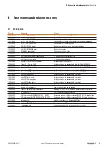

7 Example applications
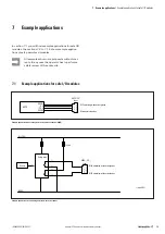
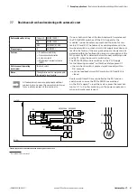
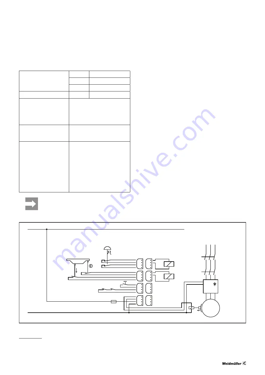
| Dual-channel safety door monitoring with automatic reset and controlled shutdown and emergency stop
87
u-remote IP20 modules for functional safety manual
1484600000/04/06.2017
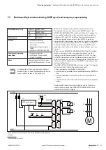
Achievable safety rating
Category 4
EN ISO 13849-1
PLe
EN ISO 13849-1
SIL 3
EN 62061/61508
Stop category
1
EN 60204-1
Features
–
Dual-channel monitoring
–
Cross-connection detection
–
Automatic reset
–
Monitoring of external contactors
(EDM)
Safety sensor / operating
mechanism
–
Emergency stop button
–
Position switch
–
Optional: brake
Notes
–
Autostart is also possible if the NC
circuits from K3 and K4 are connected
to 3.3 and 3.4.
–
As soon as the enabling on the
frequency converter is withdrawn, the
converter must execute a controlled
shutdown.
–
Exclusion of fault: No external energy
might be fed into the control line of
the brake (e. g. caused by cable fault)
All examples shown are proposals without
warranty. In any case the operator has to per-
form a safety review of the entire site.
1.1
1.2
1.3
1.4
3.1
3.2
3.3
3.4
4.1
4.2
4.3
4.4
1.1
1.2
1.3
1.4
2.1
2.2
2.3
2.4
2.1
2.2
2.3
2.4
3.1
3.2
3.3
3.4
4.1
4.2
4.3
4.4
M
UR20-PF-O-2DI-SIL-DLY UR20-4DO-P
K4
K3
K4
K3
S1
S3
S2
L+(+24V)
M (0V)
Reset
K4
K3
Emergency stop
Safety door
(closed)
Enable
Converter
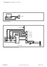
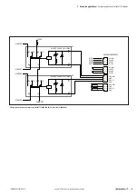
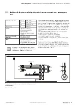
Example application for dual-channel safety door monitoring with automatic reset and controlled
shutdown and emergency stop
1)
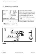
Switchable modules see section 4.3
When the emergency stop button is pushed, the
PF-O-xDI-SIL switches off the 24 V supply for the
mod-
ules
1)
within the safety segment and thus also contactors K3
and K4. The failure of a switching element in the emergency
stop button or the safety door contact as well as a cross-cir-
cuit in their supply lines does not result in the failure of the
emergency stop mechanism and is detected within the
fault-reaction time.
After opening the safety door and the expiration of the delay
time set in the UR20-PF-O-2DI-SIL-DELAY, the spring-oper
-
ated interlock can be activated with the unlock button and
the safety door can be opened. When the power supply is
turned off, the safety door cannot be opened if the locking
mechanism is engaged. We recommend using switches with
mechanical unlocking capabilities.
The PF-O-xDI-SIL module switches the 24 V power
supply for the following modules
1)
within the safety segment
if
–
the emergency stop button is unlocked
–
and the safety door is closed
–
and the feedback circuit (NC contacts of K3 and K4) is
closed.
Contactors K3 and K4 are controlled by the PLC and can
switch on as soon as the PF-O-xDI-SIL has switched
on the 24 V supply.
To reset the system, press the reset but-
ton for 0.1 to 2 s after switching on the power supply, even
when automatic reset is used.
7.13 Dual-channel safety door monitoring with automatic reset and controlled shutdown and emer-
gency stop
Summary of Contents for UR20-4DI-4DO-PN-FSOE
Page 1: ...Remote I O system u remote IP20 modules for functional safety Manual Original Letʼs connect ...
Page 8: ...8 1484600000 04 06 2017 u remote IP20 modules for functional safety manual ...
Page 20: ...20 1484600000 04 06 2017 u remote IP20 modules for functional safety manual ...
Page 70: ...70 1484600000 04 06 2017 u remote IP20 modules for functional safety manual ...
Page 72: ...72 1484600000 04 06 2017 u remote IP20 modules for functional safety manual ...
Page 96: ...96 1484600000 04 06 2017 u remote IP20 modules for functional safety manual ...
Page 102: ...ANNEX A 6 1484600000 04 06 2017 u remote IP20 modules for functional safety manual ...
Page 103: ...ANNEX A 7 1484600000 04 06 2017 u remote IP20 modules for functional safety manual ...
Page 104: ...ANNEX A 8 1484600000 04 06 2017 u remote IP20 modules for functional safety manual ...
Page 105: ...ANNEX A 9 1484600000 04 06 2017 u remote IP20 modules for functional safety manual ...
Page 106: ...ANNEX A 10 1484600000 04 06 2017 u remote IP20 modules for functional safety manual ...
Page 107: ...ANNEX A 11 1484600000 04 06 2017 u remote IP20 modules for functional safety manual ...
Page 108: ...ANNEX A 12 1484600000 04 06 2017 u remote IP20 modules for functional safety manual ...
Page 109: ...ANNEX A 13 1484600000 04 06 2017 u remote IP20 modules for functional safety manual ...
Page 110: ...ANNEX A 14 1484600000 04 06 2017 u remote IP20 modules for functional safety manual ...
Page 111: ...ANNEX A 15 1484600000 04 06 2017 u remote IP20 modules for functional safety manual ...
Page 112: ...ANNEX A 16 1484600000 04 06 2017 u remote IP20 modules for functional safety manual ...
Page 113: ...ANNEX A 17 1484600000 04 06 2017 u remote IP20 modules for functional safety manual ...
Page 114: ...ANNEX A 18 1484600000 04 06 2017 u remote IP20 modules for functional safety manual ...
Page 115: ...ANNEX A 19 1484600000 04 06 2017 u remote IP20 modules for functional safety manual ...
Page 116: ...ANNEX A 20 1484600000 04 06 2017 u remote IP20 modules for functional safety manual ...
Page 117: ...ANNEX A 21 1484600000 04 06 2017 u remote IP20 modules for functional safety manual ...
Page 118: ...ANNEX A 22 1484600000 04 06 2017 u remote IP20 modules for functional safety manual ...
Page 119: ...ANNEX A 23 1484600000 04 06 2017 u remote IP20 modules for functional safety manual ...
Page 120: ...ANNEX A 24 1484600000 04 06 2017 u remote IP20 modules for functional safety manual ...
Page 121: ...ANNEX A 25 1484600000 04 06 2017 u remote IP20 modules for functional safety manual ...
Page 122: ...ANNEX A 26 1484600000 04 06 2017 u remote IP20 modules for functional safety manual ...
Page 124: ...A 28 1484600000 04 06 2017 u remote IP20 modules for functional safety manual ...


