background image

 Ablängmaschine / Cutting machine  


 Cutfix 8  

cutfix8.doc / Mai-05


0

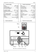
Computer

Bedienteil
Control unit

Netzfilter-Modul
Filter modul

Netzschalter
Mains switch

Sicherung
Fuse

Netzstecker
Mains plug

I


Bild / Picture 2: Hinteransicht / Back view 


5. Bedienungsanleitung 

5.1 Inbetriebnahme 

  Den Halter für das Bedienteil anschrauben. 

  Das Bedienteil einsetzen und das Kabel an die 

Maschine anschließen. 

  Das Netzkabel an die Maschine und an die 

Stromversorgung anschließen. (Die Daten auf 
dem Typenschild müssen mit dem Stromnetz 
übereinstimmen.) 


5. Operating 

instruction 

5.1 Putting 

into 

operation 

  Screw on the holder of the control unit. 

  Put in the control unit and plug the cable. 

  Connect the mains cable to the machine and 

the electrical supply. (The data on the type 
plate must agree with the mains supply.) 


5.2 Maschine 

einschalten 

 Den Netzschalter auf dem Netzfilter-Modul 

einschalten. 

 Das Standard-Menü wird geöffnet und im 

Display erscheint das Untermenü 1 Programm 
mit der Programm-Nummer. 


5.2 

Starting the machine 

  Actuate the main switch on the filter module. 

  The standard menu is opened and the sub-

menu 1 program with the program number 
appears in the display. 


5.3 Draht 

einlegen 

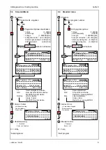
 Rollenstellung: 


  Draht durch die Drahteinführung einführen, bis 

er rechts neben den Messern erscheint. 

 Rollenstellung: 


5.3 

Put in the wire 

  Position of the rollers: 


  Insert the wire through the wire feeding until it 

appears on the right side of the blades. 

  Position of the rollers: 


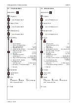
Summary of Contents for Cutfix

Page 1: ...Interface GmbH Co Klingenbergstra e 16 D 32758 Detmold Telefax 05231 14 0 Telefon 05231 14 20 83 Betriebsanleitung Operating Manual Abl ngmaschine Cutting machine Cutfix 8 Fabrikationsnummer Fabricat...

Page 2: ...ral safety notices 3 2 Information 3 3 Technical specifications 4 4 General view of the machine 4 5 Operating instruction 5 5 1 Putting into operation 5 5 2 Starting the machine 5 5 3 Put in the wire...

Page 3: ...gepr ft Es kann jedoch keine Gew hrleistung bez glich der Fehlerfreiheit bernommen werden Technische nderungen bleiben dem Hersteller vorbehalten 1 General safety notices Warning Before any work is ca...

Page 4: ...supply 230 V 50 Hz Power consumption 120 VA Fuse filter module 2 x 2 AmT Fuse control board 10 AT Multicore conductor 0 08 10 mm Single core conductor 0 08 2 5 mm Maximal outside diameter 8 mm Length...

Page 5: ...t in the control unit and plug the cable Connect the mains cable to the machine and the electrical supply The data on the type plate must agree with the mains supply 5 2 Maschine einschalten Den Netzs...

Page 6: ...n Status Fehler ok Maschine stop Fehlermeldung Produktion Kabel entfernen Status Fehler Handsteuerung Vorschub Enter schneiden F1 Hilfe Kurzprogramm 5 4 Standard menu 1 1 200 SHIFT Enter Enter 3 4 1 1...

Page 7: ...chneidmotor KB Kabelende EX externe Eing nge siehe Standard Men siehe Standard Men siehe Standard Men Netzschalter F1 Hilfe 5 5 Extended menu 1 3 4 5 6 7 ENC Incremental Code Program Status Error Manu...

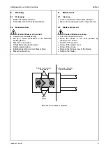
Page 8: ...ie Messer in die vorderste Stellung fahren Maschine ausschalten Schutzabdeckung abschrauben Rutsche abschrauben Befestigungsschrauben der Messer l sen Messer austauschen 6 2 Blade replacement Caution...

Page 9: ...Das zuletzt produzierte Drahtst ck entfernen 7 3 Error messages The error messages are shown on the display After the repair of failures and by pressing the clear button the error message is deleted...

Page 10: ...l Control unit Microschalter Drahtende Micro switch End of wire Lichtschranke Schneidmotor Light barrier Cutting motor Schneidmotor Cutting motor Vorschubmotor Feed motor Inkrementalgeber Vorschubmoto...

Page 11: ...ge der Kriterien sind internationale Dokumente insbesondere ISO IEC Leitfaden 22 1982 Information on manufacturer s declaration of conformity with standards or other technical specifications The firm...

Reviews: