1
•Modifications
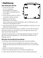
Removingthelefthandsideplate
1. Remove the six self tapping
screws marked A-F (disconnect
power first).
. Remove the two countersunk
bolts marked G & H.
3. Remove the left hand side plate
and note the position of the
insulator covering the power
supply board.
4. You can now ease the power supply board from the housing.
Warning: take great care when operating AC powered instruments
without the housing as there are high voltages present.
Note: bolt the power supply board and insulator to the side plate
before reassembly.
Removingtheelectronicsfromthehousing
1. Remove the left hand side plate as described above.
. Remove the six self tapping screws from the right hand side plate
(equivalents of A thru F on the left side).
3. Remove the front cover.
4. Slide the base extrusion off the terminal board.
. Remove the two bolts from the right hand side plate
(equivalent of G & H on the left side). Note the position of the insulator.
Assembly is the reverse of the disassembly procedure.
Warning: Correct insulator location is essential to product safety.
LEFT HAND SIDE V EW
E
B
A
C
F


