background image

•Modifications

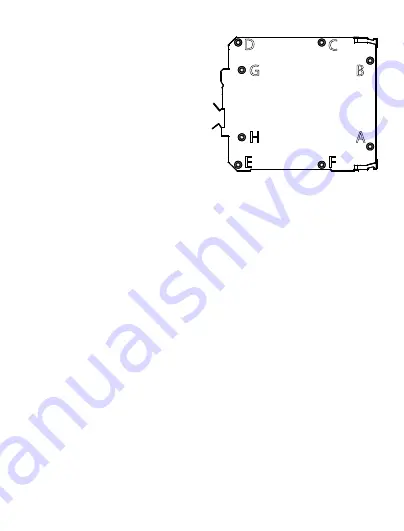
Removingthelefthandsideplate

1.  Remove the six self tapping 

screws marked A­F (turn power 
off first).

.  Remove the two countersunk 

bolts marked G & H.

.  Remove the left hand side plate 

and note the position of the 
insulator covering the power 
supply board.

4.  You can now ease the power supply board from the housing.

Warning: take great care when operating AC powered instruments 
without the housing as there are high voltages present.
Note: bolt the power supply board and insulator to the side plate 
before reassembly.

Removingtheelectronicsfromthehousing

1. Remove the left hand side plate as described above.
.  Remove the six self tapping screws from the right hand side plate 

(equivalents of A thru F on the left side).

. Remove the front cover.
4. Slide the base extrusion off the terminal board.
. Remove the two bolts from the right hand side plate
(equivalent of G & H on the left side). Note the position of the insulator.
Assembly is the reverse of the disassembly procedure.
Warning: Correct insulator location is essential to product safety.

LEFT HAND SIDE V EW

E

B

A

C

F

Summary of Contents for DPA/RTD

Page 1: ...de en DPA RTD 61001040 00 04 08 Bedienungsanleitung Zweikanaliges Grenzwertüberwachungsmodul 3 Operating instructions Two channel threshold monitoring module 15 ...

Page 2: ... ...

Page 3: ... de DPA RTD Inhaltsverzeichnis Betrieb 4 Installation 7 Kalibrierung und Konfiguration 9 Modifizierung 12 ...

Page 4: ...enkompensation ausgestattet Die Geräte werden speziell für den Einsatz innerhalb eines bestimmten Temperaturbereichs und für bestimmte RTD Temperatursensoren konzipiert Konfiguration Das Schaltverhalten der Alarmrelais wird über die Sollwerte Totbänder bestimmt die über Wendelpotentiometer an der Frontplatte konfiguriert werden Die Alarmfunktion obere und untere Schaltschwelle sowie DPA RTD Blocks...

Page 5: ...ls interner Steckbrücken festgelegt LED Anzeige Die Status LEDs an der Frontplatte zeigen unabhängig von der Einstellung der Spulenerregung die Alarmzustände an Isolierung Eingangskreis Stromversorgung Alarmkanal 1 und Alarmkanal 2 sind jeweils voneinander isoliert ...

Page 6: ...er Alarmkanal 1 Relaiskontakte 12 Wurzelkontakt 13 Schließer 14 Öffner Alarmkanal 2 Relaiskontakte 15 Wurzelkontakt 16 Schließer Schutzerde Über einen Gewindebolzen an der Unterseite des Gehäuses Hinweis 1 Doppellinien weisen auf eine Isolierung zwischen den Ports hin Vorsicht Gefahr eines Stromschlags Schraubklemmen können unter Hochspannung stehen ...

Page 7: ...landesspezifischen Bestimmungen und Sicherheitsvorschriften zu beachten Montieren Sie das Gerät in einer staubfreien trockenen Umgebung in der keine korrodierenden Gase auftreten Verschmutzungsgrad II oder besser Anforderungen an die Stromversorgung Bevor Sie das Gerät an die Stromversorgung anschließen überprüfen Sie anhand der Typenbezeichnung ob die Stromversorgung für das Gerät geeignet ist DP...

Page 8: ...pulen auftreten Zum Schutz der Relaiskontakte und benachbarter Schaltkreise ist es wichtig induktive Lasten über parallel geschaltete Kondensatoren zu entstören Die Alarmausgänge sind bereits über integrierte Kondensatoren zwischen Schließer und Wurzelkontakt geschützt Kabelkonfektionierung und installation Als effektiven Schutz vor elektromagnetischer Störeinstrahlung müssen alle Signalleitungen ...

Page 9: ...en Regler nur in seltenen Fällen notwendig ist finden Sie nachfolgend die entsprechende Vorgehensweise Anforderungen an die Betriebsmittel Ein geeigneter RTD Simulator Schlitzschraubendreher Klingenstärke weniger als 2 54 mm 0 1 Inch Klemmenbelegung für die Kalibrierung Signaltyp Klemme Eingangssignal RTD Simulator A 2 RTD Simulator B 3 RTD Simulator Leitungs widerstand B 4 Stromversorgung Neutral...

Page 10: ...n Regler SET ein 2 Stellen Sie das Totbandmaximum ein indem Sie den Regler DB im Uhrzeigersinn bis zum Anschlag drehen 3 Lösen Sie den Alarm aus indem Sie das Eingangssignal für die obere Schaltschwelle auf Full Scale Vollaussteuerung bzw für die untere Schaltschwelle auf Zero Null setzen 4 Stellen Sie den Eingang auf den Pegel ein bei dem der Alarm zurückgesetzt werden soll 5 Reduzieren Sie der T...

Page 11: ...men Sie die Elektronikbaugruppe aus dem Gehäuse heraus 2 Schließen Sie den Alarm wie in der Tabelle oben angegeben an 3 Schließen Sie den 100 Ω Widerstand zwischen Klemme 4 und dem Leitungssimulationsanschluss B an 4 Stellen Sie den RTD Simulator auf 0 C ein 5 Justieren Sie VR1 so lange bis die Spannung über den Anschlussklemmen 2 und 3 das Zweifache des Spannungsabfalls über dem Widerstand beträg...

Page 12: ... an Geräten die aus dem Gehäuse entfernt worden sind ist auf Grund der anliegenden Spannung besondere Vorsicht geboten Hinweis Schrauben Sie vor dem Wiederzusammenbau zunächst die Stromversorgungsplatine und das Isolationsmaterial an der Seitenwand fest Elektronik aus dem Gehäuse herausnehmen 1 Entfernen Sie die linke Seitenwand wie oben beschrieben 2 Lösen Sie die sechs Schneidklemmschrauben an d...

Page 13: ... an der linken Seite Merken Sie sich die Lage des Isoliermaterials Der Zusammenbau erfolgt in umgekehrter Reihenfolge Warnung Zur Gewährleistung der Produktsicherheit ist unbedingt auf eine korrekte Lage des Isoliermaterials zu achten ...

Page 14: ...nktionen Brücken für die Auswahl der Relaisspulenerregung Kanal 1 abgebildet in Position normalerweise erregt Kanal 2 abgebildet in Position normalerweise nicht erregt Brücken für die Auswahl der Alarmfunktion Kanal 2 obere Schaltschwelle ausgewählt Kanal 1 untere Schaltschwelle ausgewählt ...

Page 15: ...15 en DPA RTD Contents Operation 16 Installation 18 Calibration and Setup 19 Modifications 22 ...

Page 16: ...ensate for lead resistance They are specially built to suit a particular temperature range and RTD type Setup The alarm relay coils operate according to each setpoint deadband configured via front panel multiturn potentiometers Internal push fit jumpers determine the alarm type high or low acting and coil energisation normally energised de energised DPA RTD block diagram Alarm 1 Power Supply RTD T...

Page 17: ...l Signal 1 Not Used 2 A RTD connections 3 B 4 Bsense 5 Not Used 6 7 8 9 Neutral Power supply 10 Live 11 Normally Closed Alarm channel one Relay Contacts 12 Common 13 Normally Open 14 Normally Closed Alarm channel two Relay Contacts 15 Common 16 Normally Open Protective Earth Via stud on the underside of the case Note 1 Double lines indicate isolation between ports Caution risk of electric shock sc...

Page 18: ... followed Locate the instrument in an area that is free from dust moisture and corrosive gases pollution degree II or better Power Supply Requirements Check the power supply against the model number before applying power to the instrument Protective Earth connection Earth connections attach to a stud on the underside of the case You must attach this connection before applying power to the unit DPA...

Page 19: ...aration and installation For effective protection from electromagnetic noise all signal cables must be shielded or located on conductive trays or in conduits Use 12 28 AWG Cu Wire rated for temperatures above 70 C Only tighten to 4 5 lb In Strip wires to 7 mm from the ends Use a suitable ferrule for multistranded wires do not solder Calibration and Setup General The SET setpoint and DB deadband ad...

Page 20: ...w type alarms you turn the control clockwise to trip the alarm and anticlockwise to reset it The procedure for adjustment is as follows 1 Connect up the instrument according to the table above 2 Set the input source to the trip point 3 Turn the SET control anti clockwise until the LED extinguishes 4 Slowly turn the SET control clockwise until the LED lights up Deadband DB Control adjustment The de...

Page 21: ...rm type or coil energisation 1 Remove the left hand side plate 2 Set the links according to the diagram right 3 Replace the side plate Lead Length Compensation Adjustment factory setting Note you will require an accurate 100 Ω resistor in addition to the requirements above The procedure for adjusting this control is 1 Remove the electronics from the housing 2 Connect up the alarm according to the ...

Page 22: ...resent Note bolt the power supply board and insulator to the side plate before reassembly Removing the electronics from the housing 1 Remove the left hand side plate as described above 2 Remove the six self tapping screws from the right hand side plate equivalents of A thru F on the left side 3 Remove the front cover 4 Slide the base extrusion off the terminal board 5 Remove the two bolts from the...

Page 23: ...relay coil energisation selection jumpers Relay energisation selection jumpers Channel one Shown in normally energised position Channel two Shown in normally de energised position Trip action selection jumpers Channel two High alarm selected Channel one Low alarm selected ...

Page 24: ...Weidmüller Interface GmbH Co KG Postfach 3030 32720 Detmold Klingenbergstraße 16 32758 Detmold Tel 49 5231 14 0 Fax 49 5231 14 20 83 info weidmueller com www weidmueller com 61001040 00 04 08 ...

Reviews: