background image


Crimpanweisungen 

2635530000/00/10.2018 


15 

4.


Crimpanweisungen

Mindestanzahl der erforderlichen Crimpungen beim Verarbeiten von 

Weidmüller Kabelschuhen und Verbindern. Bei Verbindern gilt die 

erforderliche Mindestanzahl je Seite. 


DIN 46235 und DIN 46267 


Querschnitt 

in mm² 

Kennzahl 

Crimpungen 

Anzahl  x  Breite 

1 x 7 mm 

10 

1 x 7 mm 

16 

1 x 12 mm 

25 

10 

1 x 12 mm 

35 

12 

2 x 5 mm 

50 

14 

3 x 5 mm 

70 

16 

3 x 5 mm 

95 

18 

4 x 5 mm 

120 

20 

4 x 5 mm 

150 

22 

4 x 5 mm 

185 

25 

4 x 5 mm 

240 

28 

4 x 5 mm 

300 

32 

4 x 5 mm 


Summary of Contents for HPG 60

Page 1: ...Hydraulisches Crimpwerkzeug HPG 60 Hydraulic crimping tool HPG 60 Betriebs und Wartungsanleitung 3 Operating and maintenance instruction 19 Seriennummer Serial number ...

Page 2: ...2 2635530000 00 10 2018 Weidmüller Interface GmbH Co KG Klingenbergstraße 16 32758 Detmold Germany Tel 49 0 5231 14 0 Fax 49 0 5231 14 292083 www weidmueller com ...

Page 3: ...Bestimmungsgemäßer Gebrauch 6 1 3 Fachpersonal 6 2 Produktbeschreibung 8 2 1 Technische Daten 9 3 Bedienung 10 3 1 Einsetzen und Ausbauen der Crimpeinsätze 10 3 2 Vorbereitungen des zu bearbeitenden Kabels 12 3 3 Crimpvorgang 13 4 Crimpanweisungen 15 5 Wartung 17 6 Störungsbehebung 18 ...

Page 4: ...zes greifen WARNUNG Bei Nichtbeachtung besteht Lebensgefahr Arbeiten Sie niemals an unter Spannung stehenden Leitungen Die Spannungsfreiheit ist vor dem Arbeitsbeginn sicherzustellen und mit geeigneten Mitteln zu prüfen VORSICHT Beim Vorfahren des Kolbens besteht Quetschgefahr VORSICHT Es dürfen keinerlei Veränderungen am Crimpwerkzeug vorge nommen werden ...

Page 5: ...n ob die beiden Hälften des Crimpeinsatzes vollständig aufeinander liegen Erst dann ist eine ord nungsgemäße Crimpung garantiert Stellen Sie vor Arbeitsbeginn sicher dass die Klinke vollständig in das Schwenkjoch eingerastet ist Beachten Sie unbedingt die Anzahl der Crimpungen an der Verbindungs technik Diese Betriebsanleitung muss ständig am Einsatzort des Werkzeuges zur Verfügung stehen Es ist s...

Page 6: ... in explosionsgefährdeter Umgebung Eine andere Verwendung ist nicht bestimmungsgemäß und daher nicht zuläs sig Die Bedingungen dieser Betriebsanleitung sind unbedingt zu beachten 1 3 Fachpersonal Diese Bedienungsanleitung wendet sich an ausgebildetes Fachpersonal das sich mit den geltenden Bestimmungen und Normen des Verwendungsbe reichs auskennt 1 4 Recycling nach WEEE Entsorgung BtoB Mit dem Erw...

Page 7: ...hr Gerät nach der aktuellen Gesetzeslage fachgerecht recyceln und entsorgen Was müssen Sie tun Nachdem Ihr Gerät sein Lebensende erreicht hat senden Sie es einfach per Parcelservice im Karton an das Weidmüller Tochterunternehmen welches Sie betreut wir übernehmen dann alle anfallenden Recycling und Entsor gungsmaßnahmen Ihnen entstehen dadurch keine Kosten und Unannehm lichkeiten ...

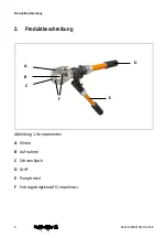
Page 8: ...Produktbeschreibung 8 2635530000 00 10 2018 2 Produktbeschreibung Abbildung 1 Komponenten A Klinke B Aufnahme C Schwenkjoch D Griff E Pumphebel F Entriegelungsknopf Crimpeinsatz C F D B E A ...

Page 9: ...Produktbeschreibung 2635530000 00 10 2018 9 2 1 Technische Daten Länge ca 500 mm Gewicht ca 4 35 kg Crimpkraft ca 60 kN ...

Page 10: ... und Querschnittszuordnung unter Auswahl der Crimpeinsätze 3 1 Einsetzen und Ausbauen der Crimpeinsätze ACHTUNG Es ist unbedingt darauf zu achten dass die verwendeten Crimp einsätze sowohl vom Querschnitt als auch vom Typ für die Ka belschuhe bzw Verbinder geeignet sind Eine falsche Zuordnung führt zu mangelhaften elektrischen und mechanischen Verbindungen zwischen Kabelschuh und Kabel o der Verbi...

Page 11: ...mit Einsatzpaar 3 Legen Sie die Crimpeinsatzhälften nacheinander in die Aufnahmen des Crimpkopfes ein 4 Schieben Sie die Hälften der Crimpeinsätze seitlich soweit in das Schwenk joch bzw die Aufnahme bis die Kugeln die Crimpeinsatzhälften klemmen Stellen Sie den festen Sitz der Crimpeinsatzhälften vor Arbeitsbeginn si cher 5 Schließen Sie den Crimpkopf bis die Klinke einrastet 6 Zum Ausbau der Cri...

Page 12: ...res Arbeiten ist nicht mehr gewährleis tet 3 2 Vorbereitungen des zu bearbeitenden Kabels Das Kabel ist rechtwinklig zum Leiter abzuschneiden 1 Entfernen Sie die Isolierung des Kabels entsprechend der Hülsenlänge a Maß des Kabelschuhs Verbinders zzgl 10 2 Reinigen Sie die Leiterenden gründlich von jeglichem Schmutz und Oxydresten 3 Sektorleiter müssen vor dem Crimpvorgang vorgerundet werden ...

Page 13: ... Kabelschuhs Verbinders einführen 5 Durch weitere Pumpbewegungen wird der Crimpvorgang fortgeführt Die Crimpung ist beendet sobald die automatische Druckbegrenzung auslöst ein akustischer Klick zu hören ist und der Pumphebel sich leicht durch drücken lässt Die beiden Crimpeinsatzhälften sollten jetzt vollständig auf einander liegen 6 Zum Öffnen der Crimpeinsätze ist der Pumphebel siehe Abbildung 1...

Page 14: ...notwendig ist an der Flanschseite beginnend zum Hülsenende zu crimpen siehe Abbildung 3 auf Seite 14 Die Mindestanzahl der Crimpungen kann aus den aktuellen Weidmüller Crimpanweisungen ent nommen werden Bei Verbindern ist die Anzahl der Crimpungen auf jeder Seite durchzuführen Abbildung 3 Arbeitsrichtung beim Vercrimpen Crimpeinsatz Crimpeinsatz Crimpen ...

Page 15: ...und Verbindern Bei Verbindern gilt die erforderliche Mindestanzahl je Seite DIN 46235 und DIN 46267 Querschnitt in mm Kennzahl Crimpungen Anzahl x Breite 6 5 1 x 7 mm 10 6 1 x 7 mm 16 8 1 x 12 mm 25 10 1 x 12 mm 35 12 2 x 5 mm 50 14 3 x 5 mm 70 16 3 x 5 mm 95 18 4 x 5 mm 120 20 4 x 5 mm 150 22 4 x 5 mm 185 25 4 x 5 mm 240 28 4 x 5 mm 300 32 4 x 5 mm ...

Page 16: ...2018 Euro Serie Querschnitt in mm Crimpungen Anzahl x Breite 6 1 x 7 mm 10 1 x 7 mm 16 1 x 7 mm 25 1 x 12 mm 35 2 x 5 mm 50 2 x 5 mm 70 2 x 5 mm 95 2 x 5 mm 120 3 x 5 mm 150 3 x 5 mm 185 3 x 5 mm 240 3 x 5 mm 300 4 x 5 mm ...

Page 17: ...Teile des Werkzeuges sollen regelmäßig gereinigt und gefettet werden Zusätzlich sind alle Teile auf Beschädigungen und Verschleiß zu kontrollieren Das Werkzeug muss trocken gelagert werden Betrug die Lagertemperatur für längere Zeit weniger als 5 C sollte das Gerät vor dem Einsatz mindestens eine Stunde auf Raumtemperatur erwärmt werden Das Werkzeug sollte nicht bei Temperaturen über 60 C gelagert...

Page 18: ...icht komplett zurück gefahren Betätigen Sie den Ölrücklauf siehe unter Crimpvorgang Der Crimpkopf lässt sich nicht drehen Das Werkzeug ist nicht drucklos Betätigen Sie den Ölrücklauf siehe unter Crimpvorgang Die Crimpeinsätze bleiben während des Crimpvorganges stehen oder bewegen sich vor und zurück Pumpbewegung fortsetzen bis die autom Druckregelung mehrmals auslöst Ölrücklauf einleiten Diesen Vo...

Page 19: ...ended use 22 1 3 Qualified staff 22 1 4 Recycling in accordance with WEEE 22 2 Product description 24 2 1 Technical data 25 3 Operating 26 3 1 Insertion and removal of the dies 26 3 2 Preparation of the conductor 28 3 3 Process of crimping 28 4 Crimping instructions 30 5 Maintenance 32 6 Troubleshooting 33 ...

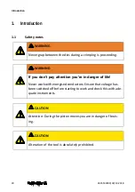
Page 20: ...ng WARNING If you don t pay attention you re in danger of life Never work with energised conductors Ensure that voltage has been switched off before starting to work and check this with ade quate instruments CAUTION Attention During the piston moves you are in danger of bruis ing CAUTION Alteration of the tool is absolutely prohibited ...

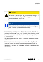
Page 21: ...rimping control whether the two halves of the dies lie completely on top of each other Only this guarantees an accurate crimping Before starting to work control that the latch has been snapped in the shackle completely Pay attention to the necessary number of crimpings illustrated on the con nection material This instruction manual has always to be available when using the tool Take care that only...

Page 22: ...ded and therefore not permitted The instructions given in this manual must be absolutely followed 1 3 Qualified staff These operating instructions have been written for trained and qualified per sonnel who are familiar with the valid regulations and standards applicable to the field of application 1 4 Recycling in accordance with WEEE BtoB disposal Purchasing our product gives you the opportunity ...

Page 23: ... then professionally recycle and dispose of your device in accordance with the actual laws What do you have to do Once your device has reached the end of its life cycle simply return it in the carton to the Weidmüller sales agent responsible for you We will then take care of all recycling and waste disposal measures You will incur no costs or suffer any inconvenience ...

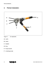
Page 24: ...Product description 24 2635530000 00 10 2018 2 Product description Figure 1 Components A Latch B Collet C Shackle D Grip E Pump handle F Unlocking knob A D B E C F ...

Page 25: ...Product description 2635530000 00 10 2018 25 2 1 Technical data Length ca 500 mm Weight ca 4 35 kg Crimp capacity ca 60 kN ...

Page 26: ...hat the used dies absolutely fit to the cable lugs and connectors with respect to the cross section as well as the type of forming Wrong combinations lead to insufficient electrical and mechani cal connections between cable lugs and conductor or connectors and conductor On principle these crimp instructions are valid for stranded conductors only For crimping on solid conductors please consult Weid...

Page 27: ...h the dies carefully from the side into the collet until the bullet slips in the track of the dies Make sure that the dies have snapped in correctly before processing 5 Close the shackle until the latch snaps in 6 To remove the dies open push the unlocking knob push them carefully to the side NOTICE The latch has to be snapped in completely before starting to crimp Otherwise the bolting device wil...

Page 28: ...in danger of bruising 1 Insert the connection material between the dies For this purpose open the crimp head if necessary Don t cant the cable lug or connector be tween the dies cable lug connector and crimp head are intended to be right angled 2 Turn the grip see Figure 1 on page 24 into the position for the pressure build up 3 Some movements of the pump handle will fix the cable lug connector se...

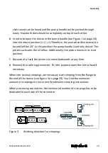
Page 29: ...s activates the oil reflux Additionally the piston moves in its start position 7 Because of a fault the piston can move backwards at any time 8 Remove the cable lug connector For this purpose open the crimp head if necessary Whenever several crimpings are necessary start crimping from the flange to the end of the sleeve see Figure 3 on page 29 You find the minimum amount of crimpings in the curren...

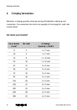
Page 30: ...or connectors the minimum quantity of crimpings for each side is mentioned DIN 46235 and DIN 46267 Cross section in mm Die code Crimpings Quantity x Width 6 5 1 x 7 mm 10 6 1 x 7 mm 16 8 1 x 12 mm 25 10 1 x 12 mm 35 12 2 x 5 mm 50 14 3 x 5 mm 70 16 3 x 5 mm 95 18 4 x 5 mm 120 20 4 x 5 mm 150 22 4 x 5 mm 185 25 4 x 5 mm 240 28 4 x 5 mm 300 32 4 x 5 mm ...

Page 31: ... 00 10 2018 31 Euro series Cross section in mm Crimpings Quantity x Width 6 1 x 7 mm 10 1 x 7 mm 16 1 x 7 mm 25 1 x 12 mm 35 2 x 5 mm 50 2 x 5 mm 70 2 x 5 mm 95 2 x 5 mm 120 3 x 5 mm 150 3 x 5 mm 185 3 x 5 mm 240 3 x 5 mm 300 4 x 5 mm ...
Page 32: ...h this maintenance All movable parts have to be cleaned and greased regularly Furthermore all parts have to be checked for damage and abrasion The tool must be stored in a dry area If the storage temperature has been below 5 C for a longer period the tool must be warmed up to room temperature at least for one hour before using The tool shouldn t be stored at a temperature of more than 60 C We reco...

Page 33: ...the grip into the return position see process of crimping The tool head cannot be rotated The tool is not depressurized Turn the grip into the return position see process of crimping The dies stopped during the process of crimping or move for and backwards Make pump movements with the pump lever until the pressure interruption is activate several times Move the grip into return position Repeat thi...

Page 34: ...Troubleshooting 34 2635530000 00 10 2018 ...

Reviews: