background image

Content

2

Manual maxGUARD

2526740000/02/03.2018

About this documentation 

3

1.1  Symbols and notes 

3

1.2  Complete documentation 

3

2 Safety 

4

2.1  General safety notes 

4

2.2  Intended use 

4

2.3  Use in explosive risk zones 

5

2.4  Legal notice 

5

System overview 

6

3.1  Mode of operation and connection concept 

7

3.2  Functions 

8

3.3  Type plate 

8

3.4  Markers 

9

3.5  Internal fuse 

10

3.6  Product overview 

11

3.7  General technical data 

14

3.8  Tripping characteristics 

16

3.9  Conformity and approvals 

19

Configuration 

21

4.1  Configuration in the Weidmüller Configurator 

21

4.2  Arrangement and combination of the modules 

21

4.3  Installation position and mounting distances 

22

4.4  Configuring cross-connections 

22

4.5  Earthed and non-earthed control voltage distributors 

23

4.6  Connection to the control unit 

24

4.7  Segmentation of control voltage distributors 

25

4.8  Extending control voltage distributors 

26

4.9  Example configurations 

27

Feed-in modules, control modules, alarm modules 

30

5.1  Passive feed-in modules AMG FIM-0... 

30

5.2  Active feed-in modules AMG FIM-C... 

31

5.3  Control modules AMG CM...   

32

5.4  Alarm modules AMG AM...  

33

Electronic load monitors 

34

6.1  AMG ELM-x... 

34

6.2  AMG ELM-xF... 

36

6.3  AMG ELM-xF CL2 

38

6.4  AMG ELM-Qxxxx 

40

6.5  AMG ELM-xD C0 

42

Potential distribution terminals 

44

7.1  AMG PD... potential distribution terminal 

44

7.2  AMG OD... potential distribution terminal 

44

7.3  AMG MD... potential distribution terminal 

45

7.4  AMG XMD... potential distribution terminal 

45

7.5  AMG DIS... potential distribution terminal 

46

Installation and wiring 

47

8.1  Preparations for installation 

47

8.2  Installing the maxGUARD station 

48

8.3  Attaching markers 

50

8.4  Installing cross-connectors 

50

8.5  Wiring 

51

8.6  Insulation tests 

52

9 Operation 

53

9.1  Commissioning 

53

9.2  Switching load monitors on/off 

53

9.3  Resetting load monitors 

54

9.4  Setting a new characteristic 

54

10  Disassembly and disposal 

55

10.1  Required tools 

55

10.2  Disassembling a module 

55

10.3  Disassembling a maxGUARD station 

55

10.4  Disposing of a maxGUARD station 

56

11  LED indicators and troubleshooting 

57

ANNEX A-1

Normal tripping characteristic 1A

N


A-2

Normal tripping characteristic 2A

N


A-3

Normal tripping characteristic 3A

N


A-4

Normal tripping characteristic 4A

N


A-5

Normal tripping characteristic 6A

N


A-6

Normal tripping characteristic 8A

N


A-7

Normal tripping characteristic 10A

N


A-8

Normal tripping characteristic 12A

N


A-9

Normal tripping characteristic 1A

CL2


A-10

Normal tripping characteristic 2A

CL2


A-11

Normal tripping characteristic 4A

CL2


A-12

Lagged tripping characteristic 1A

T


A-13

Lagged tripping characteristic 2A

T


A-14

Lagged tripping characteristic 3A

T


A-15

Lagged tripping characteristic 4A

T


A-16

Lagged tripping characteristic 6A

T


A-17

Lagged tripping characteristic 8A

T


A-18

Lagged tripping characteristic 10A

T


A-19

Lagged tripping characteristic 12A

T


A-20

Manufacturer

Weidmüller Interface GmbH & Co. KG 

Klingenbergstraße 16 

D-32758 Detmold 

T  +49 5231 14-0 

F  +49 5231 14-292083 

www.weidmueller.com

Document No.  2526740000 

Revision 

02/March 2018

Summary of Contents for maxGUARD

Page 1: ...Load monitoring with integrated potential distribution maxGUARD Manual Let s connect...

Page 2: ...terminal 45 7 4 AMG XMD potential distribution terminal 45 7 5 AMG DIS potential distribution terminal 46 8 Installation and wiring 47 8 1 Preparations for installation 47 8 2 Installing the maxGUARD...

Page 3: ...tions that may result in injury if you do not follow the instructions given in this manual ATTENTION Material damage Notes with the signal word Attention warn you of hazards that may result in materia...

Page 4: ...fuse must be designed such that it does not exceed the maximum load current The maximum permissible load current of the maxGUARD products can be found in the technical data The operator must decide wh...

Page 5: ...ectors are used AMG PP separation plates must be inserted wherever there are bare cut edges next to one another If the temperature of a conductor or conductor entry exceeds 70 C during rated operation...

Page 6: ...lue variants or with an adjustable trip ping characteristic as well as with a 2 pole output relay Active feed in modules control modules and alarm modules are used to control and monitor the electroni...

Page 7: ...uts of the load monitors as required The internal signal line enables communication within the maxGUARD station Active feed in modules control modules and alarm modules connect the internal signal lin...

Page 8: ...the module LED will quickly flash red If the input voltage of a load monitor falls below 18 V the load monitor will also disconnect the output If the input voltage falls below 15 V the module will po...

Page 9: ...400000 WS 10 6 white PA 66 Markers for printing with Weidm ller THM MMP Order No 2430820000 Order No 2007160000 WS 8 6 MM white PC ABS TPU WAD group marker The AMG PP separation plate can be fitted wi...

Page 10: ...Order No 1670400000 ESO 7 P yellow polyester 3 5 Internal fuse All load monitors are equipped with an internal fuse on the PCB If the electronic switch off fails the fuse will protect the electronics...

Page 11: ...2080480000 AMG ELM 4F 1 channel fixed value 4 A 2080490000 AMG ELM 6F 1 channel fixed value 6 A 2080500000 AMG ELM 8F 1 channel fixed value 8 A 2080600000 AMG ELM 10F 1 channel fixed value 10 A 20806...

Page 12: ...6 A 2082000000 AMG ELM 12 EX 1 channel adjustable 4 12 A 2082010000 AMG ELM 6D CO 1 channel adjustable 1 6 A 2 pole output relay 2082440000 AMG ELM 10D CO 1 channel adjustable 4 10 A 2 pole output re...

Page 13: ...poles Type Order No Type Order No Type Order No 2 pole ZQV 4N 2 1527930000 ZQV 4N 2 BL 1528040000 ZQV 4N 2 RD 2460450000 3 pole ZQV 4N 3 1527940000 ZQV 4N 3 BL 1528080000 ZQV 4N 3 RD 2460810000 4 pole...

Page 14: ...of load connections max 12 A total current load monitors potential distribution terminals Connections Connection type all line connections PUSH IN 16 mm connections feed in module Clamping range rigid...

Page 15: ...0 MHz 80 AM Functional earth 10 V 0 15 80 MHz 80 AM HF field EN 61000 4 3 Enclosure 10 V m 80 1000 MHz 3 V m 1 4 GHz 2 GHz 1 V m 2 GHz 2 7 GHz Shock resistance according to EN 60068 2 27 Test Ea 15 g...

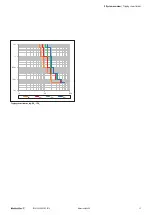
Page 16: ...ions and numerical values for the individual characteristics can be found in the annex PV PV PV V V 1 1 1 1 Tripping characteristics normal 1AN 4AN 1 1 1 1 PV PV PV V V Tripping characteristics normal...

Page 17: ...17 Manual maxGUARD 2526740000 02 03 2018 3 System overview Tripping characteristics 7 7 7 7 PV PV PV V V Tripping characteristics lag 6AT 12AT...

Page 18: ...2080360000 AMG ELM 12 2080410000 AMG ELM 1F 2080420000 AMG ELM 1F CL2 2491270000 AMG ELM 2F 2080480000 AMG ELM 2F CL2 2491280000 AMG ELM 4F 2080490000 AMG ELM 4F CL2 2491290000 AMG ELM 6F 2080500000...

Page 19: ...AMG ELM 6 2080360000 AMG ELM 12 2080410000 AMG ELM 1F 2080420000 AMG ELM 1F CL2 2491270000 AMG ELM 2F 2080480000 AMG ELM 2F CL2 2491280000 AMG ELM 4F 2080490000 AMG ELM 4F CL2 2491290000 AMG ELM 6F 2...

Page 20: ...082310000 AMG ELM 8F EX 2082320000 AMG ELM 10F EX 2082430000 AMG PD EX 2495070000 AMG OD EX 2495090000 AMG MD EX 2495040000 AMG XMD EX 2495080000 AMG DIS EX 2495100000 IND CONT EQ E258476 Poll Deg 2 T...

Page 21: ...dules Control modules should be positioned next to a passive feed in module or at the beginning of a segment Control modules must be connected to the internal signal line and both main strands Control...

Page 22: ...a cross connectors To this end only the ZQV 4N x cross connectors specified in section 3 6 shall be used Whenever possible use uncut cross connectors in sulated on both sides The use of different colo...

Page 23: ...edges next to one another ATTENTION Risk of malfunction Do not connect multiple load monitors in parallel or in series Never connect the signal contacts of the control mod ules and alarm modules to t...

Page 24: ...erminal may not be used for contact replication in the case of load monitors with a 2 pole output relay This would render the functional isolation at the MINUS output ineffective 24 V GND 1 2 3 4 24 V...

Page 25: ...ent and may not be connected to the internal signal lines of other segments A segment may contain a maximum of 25 bus participants A feed in module connects the power supply to the entire maxGUARD sta...

Page 26: ...new and the original cross connectors are electri cally connected In this way the new cross connector will begin at an active cross connection socket that is already connected to the original cross co...

Page 27: ...lowing maxGUARD products are used 1x AMG FIM 0 1x AMG ELM Q2222 1x AMG XMD 1x AMG EP 2x WEW 35 2 1x ZQV 4N 6 RD 1x ZQV 4N 7 BL The passive feed in module feeds in the supply voltage The potentials are...

Page 28: ...feed in module feeds in the supply voltage and connects the station to the control unit The potentials are distributed to the individual modules via cut cross connectors As the total current flowing t...

Page 29: ...s the first segment to the control unit The second segment is connected to the control unit via the control mod ule and the alarm module The potentials are distributed to the individual modules via cu...

Page 30: ...n strand connection 24 V 2 24 V feed in connection 16 mm2 3 GND feed in connection 16 mm2 4 GND main strand connection 0 V 5 Marker The passive feed in modules are used to connect the feed in conducto...

Page 31: ...the internal signal line to an external control unit An active feed in module and the connected load monitors form unit concerning the control LED Colour Meaning PWR Green Fault free operation Red fla...

Page 32: ...age error Red Alarm tripped or internal fault ON Yellow Reset tripped or ON OFF tripped AMG CM block diagram Signal Function Type Level Reset Resets electronic load monitors Input LOW no reset HIGH re...

Page 33: ...otential free to control boards using alarm modules LED Colour Meaning AL Red Alarm tripped I Yellow Overload advance warning I 90 AMG AM block diagram Signal Function Relay NO contact I 90 Overload a...

Page 34: ...g the thumb wheel switch LED Colour Meaning LED Green Fault free operation Red Load monitor is switched off Red flashing Load monitor tripped Red flashing fast Internal error Orange red and green Over...

Page 35: ...t consumption IOUT 30 mA Voltage drop at IOUT rated 200 mV 250 mV Capacitive load 15 000 F 20 000 F Overtemperature protection Yes Width 6 1 mm 12 2 mm Tripping characteristic Adjustable Yes Tripping...

Page 36: ...connector 9 Markers 10 Internal signal line connection The AMG ELM 1F to AMG ELM 10F 1 channel electronic load monitors monitor individual load circuits and disconnect them in the event of a short ci...

Page 37: ...V DC Rated output current IOUT rated 1 A 2 A 4 A 6 A 8 A 10 A Current consumption IOUT 30 mA Voltage drop at IOUT rated 200 mV Capacitive load 10 000 F 15 000 F 20 000 F Overtemperature protection No...

Page 38: ...F CL2 AMG ELM 2F CL2 and AMG ELM 4F CL2 1 channel electronic load monitors monitor individual load circuits and disconnect them in the event of a short cir cuit or overload They are suited for use in...

Page 39: ...supply voltage 31 2 V DC Rated output current IOUT rated 1 A 2 A 4 A Current consumption IOUT 30 mA Voltage drop at IOUT rated 200 mV Capacitive load 4 700 F Overtemperature protection No Width 6 1 m...

Page 40: ...or overload The tripping current and the tripping characteristic are fixed LED Colour Meaning LED Green Fault free operation Red Load monitor switched off Red flashing Load monitor tripped Red flashin...

Page 41: ...A 2x 2 A 2x 6 A Current consumption IOUT 4 x 30 mA Voltage drop at IOUT rated 200 mV Capacitive load 10 000 F per channel 15 000 F per channel 10 000 F per channel 10 000 F per 2 A channel 15 000 F p...

Page 42: ...acteris tic are selected using the thumbwheel switch LED Colour Meaning LED Green Fault free operation Red Load monitor switched off Red flashing Load monitor tripped Red flashing fast Internal error...

Page 43: ...mA Voltage drop at IOUT rated 200 mV 250 mV Capacitive load 15 000 F 20 000 F Overtemperature protection Yes Width 18 3 mm Tripping characteristic Adjustable Yes Tripping current IT 1 A 2 A 3 A 4 A 6...

Page 44: ...S output of the AMG ELM load monitors The potential is fed in exclusively from the PLUS output of the load monitor via a cross connector AMG PD block diagram 7 2 AMG OD potential distribution terminal...

Page 45: ...te the MINUS output of the AMG ELM load monitors The potential is fed in exclusively from the MINUS output of the load monitor via a cross connector AMG MD block diagram 7 4 AMG XMD potential distribu...

Page 46: ...5 mm2 5 MINUS output connection cross connector 6 PLUS output connection cross connector 7 Marker The AMG DIS potential distribution terminal is used to repli cate the outputs of the AMG ELM load moni...

Page 47: ...7 5 e g Weidm ller TS 35X7 5 The terminal rail must be fitted before the maxGUARD station is installed The terminal rail must be attached to the substrate at inter vals of at least 20 cm to protect i...

Page 48: ...feet can be moved on both end brackets If necessary loosen the mounting screw until the terminal rail feet can be moved freely 8 2 Installing the maxGUARD station WARNING Explosion risk Before startin...

Page 49: ...ands or if the maxGUARD station ends with a potential distribution terminal Installing an end bracket with an end plate left Installing an end bracket with an end plate right End plates are not snappe...

Page 50: ...fic regulations WARNING Dangerous contact voltage Carry out installation and wiring work on the maxGUARD station only when the power supply is disconnected Make sure that the place of installation pan...

Page 51: ...ength using the cutting tool Install the cross connectors in accordance with the instal lation drawing or wiring diagram 8 5 Wiring WARNING Explosion risk Before starting any work make sure that there...

Page 52: ...indentation crimp type PZ 16 ZERT Order No 9017340000 maxGUARD modules are equipped with PUSH IN connec tions Solid and fine strand wires with wire end ferrules can be inserted without the need for to...

Page 53: ...f press the reset button R for 0 1 to 2 seconds The load monitor will switch to ready state and the LED will illuminate green While in ready state press the reset button R for 0 1 to 2 seconds The loa...

Page 54: ...d monitors in a segment using the reset signal The segment must contain an AMG CM con trol module or an AMG FIM C active feed in module To reset all load monitors in the segment set the reset input of...

Page 55: ...dules we recommend a slotted screwdriver with a blade width of 6 5 mm For all other modules we recommend a slotted screwdriver with a blade width of 3 5 mm Press down the screwdriver in the direction...

Page 56: ...ctrical and electronic equipment Make sure that the products are properly disposed of When all maxGUARD products reach the end of their life cy cle you can return them to Weidm ller and we will arrang...

Page 57: ...L Red Alarm on at least one load monitor tripped Check the LEDs on the connected load monitors Off No alarm I 90 LED I Yellow Overload advance warning on at least one load monitor tripped Check the LE...

Page 58: ...eristic 10AN A 8 Normal tripping characteristic 12AN A 9 Normal tripping characteristic 1ACL2 A 10 Normal tripping characteristic 2ACL2 A 11 Normal tripping characteristic 4ACL2 A 12 Lagged tripping c...

Page 59: ...D 2526740000 02 03 2018 Annex Normal tripping characteristic 1AN PV PV PV V V Output current 1 1 A I 2 A 2 A I 3 A 3 A I 6 A 6 A I 14 A I 14 A Tripping time 5 s 1 s 100 ms 10 ms 5 ms Normal tripping c...

Page 60: ...D 2526740000 02 03 2018 Annex Normal tripping characteristic 2AN PV PV PV V V Output current 2 2 A I 3 A 3 A I 4 4 A 4 4A I 8 A 8A I 14 A I 14A Tripping time 5 s 1 s 100 ms 10 ms 5 ms Normal tripping...

Page 61: ...D 2526740000 02 03 2018 Annex Normal tripping characteristic 3AN PV PV PV V V Output current 3 3 A I 4 A 4 A I 5 A 5 A I 9 A 9 A I 17 A I 17 A Tripping time 5 s 1 s 100 ms 10 ms 5 ms Normal tripping c...

Page 62: ...2526740000 02 03 2018 Annex Normal tripping characteristic 4AN PV PV PV V V Output current 4 4 A I 5 A 5 A I 6 A 6 A I 10 A 10 A I 18 A I 18 A Tripping time 5 s 1 s 100 ms 10 ms 5 ms Normal tripping...

Page 63: ...526740000 02 03 2018 Annex Normal tripping characteristic 6AN PV PV PV V V Output current 6 6 A I 7 4 A 7 4 A I 9 A 9 A I 14 A 14 A I 18 A I 18 A Tripping time 5 s 1 s 100 ms 10 ms 5 ms Normal trippin...

Page 64: ...26740000 02 03 2018 Annex Normal tripping characteristic 8AN PV PV PV V V Output current 8 8 A I 9 5 A 9 5 A I 14 A 14 A I 19 A 19 A I 40 A I 40 A Tripping time 5 s 1 s 100 ms 10 ms 5 ms Normal trippi...

Page 65: ...526740000 02 03 2018 Annex Normal tripping characteristic 10AN PV PV PV V V Output current 11 A I 14 A 14 A I 18 A 18 A I 20 A 20 A I 40 A I 40 A Tripping time 5 s 1 s 100 ms 10 ms 5 ms Normal trippin...

Page 66: ...26740000 02 03 2018 Annex Normal tripping characteristic 12AN PV PV PV V V Output current 13 2 A I 18 A 18 A I 20 A 20 A I 22 A 22 A I 40 A I 40 A Tripping time 5 s 1 s 100 ms 10 ms 5 ms Normal trippi...

Page 67: ...2526740000 02 03 2018 Annex Normal tripping characteristic 1ACL2 PV PV PV V V Output current 1 1 A I 2 A 2 A I 3 A 3 A I 6 A 6 A I 14 A I 14 A Tripping time 4 7 s 1 s 100 ms 10 ms 5 ms Normal tripping...

Page 68: ...26740000 02 03 2018 Annex Normal tripping characteristic 2ACL2 PV PV PV V V Output current 2 2 A I 3 A 3 A I 4 4 A 4 4 A I 8 A 8 A I 14 A I 14 A Tripping time 4 7 s 1 s 100 ms 10 ms 5 ms Normal trippi...

Page 69: ...2526740000 02 03 2018 Annex Normal tripping characteristic 4ACL2 PV PV PV V V Output current 4 A I 5 A 5 A I 6 A 6 A I 10 A 10 A I 18 A I 18 A Tripping time 4 7 s 1 s 100 ms 10 ms 5 ms Normal tripping...

Page 70: ...0000 02 03 2018 Annex Lagged tripping characteristic 1AT PV PV PV V V Output current 1 1 A I 2 A 2 A I 3 A 3 A I 6 A 6 A I 12 A 12 A I 15 A I 15 A Tripping time 5 s 1 s 100 ms 30 ms 10 ms 5 ms Lagged...

Page 71: ...00 02 03 2018 Annex Lagged tripping characteristic 2AT PV PV PV V V Output current 2 2 A I 3 A 3 A I 4 4 A 4 4 A I 8 A 8 A I 13 A 13 A I 15 A I 15 A Tripping time 5 s 1 s 100 ms 30 ms 10 ms 5 ms Lagge...

Page 72: ...0000 02 03 2018 Annex Lagged tripping characteristic 3AT PV PV PV V V Output current 3 3 A I 4 A 4 A I 5 A 5 A I 9 A 9 A I 15 A 15 A I 18 A I 18 A Tripping time 5 s 1 s 100 ms 30 ms 10 ms 5 ms Lagged...

Page 73: ...000 02 03 2018 Annex Lagged tripping characteristic 4AT PV PV PV V V Output current 4 4 A I 5 A 5 A I 6 A 6 A I 10 A 10 A I 18 A 18 A I 20 A I 20 A Tripping time 5 s 1 s 100 ms 30 ms 10 ms 5 ms Lagged...

Page 74: ...0 02 03 2018 Annex Lagged tripping characteristic 6AT PV PV PV V V Output current 6 6 A I 7 4 A 7 4 A I 9 A 9 A I 14 A 14 A I 18 A 18 A I 20 A I 20 A Tripping time 5 s 1 s 100 ms 30 ms 10 ms 5 ms Lagg...

Page 75: ...02 03 2018 Annex Lagged tripping characteristic 8AT PV PV PV V V Output current 8 8 A I 9 5 A 9 5 A I 14 A 14 A I 18 A 18 A I 28 A 28 A I 44 A I 44 A Tripping time 5 s 1 s 100 ms 30 ms 10 ms 5 ms Lag...

Page 76: ...02 03 2018 Annex Lagged tripping characteristic 10AT PV PV PV V V Output current 11 A I 14 A 14 A I 18 A 18 A I 20 A 20 A I 30 A 30 A I 48 A I 48 A Tripping time 5 s 1 s 100 ms 30 ms 10 ms 5 ms Lagge...

Page 77: ...02 03 2018 Annex Lagged tripping characteristic 12AT PV PV PV V V Output current 13 2 A I 18 A 18 A I 20 A 20 A I 24 A 24 A I 34 A 34 A I 48 A I 48 A Tripping time 5 s 1 s 100 ms 30 ms 10 ms 5 ms Lagg...

Page 78: ...and know the technological challenges of tomorrow We are therefore continuously developing innovative sustainable and useful solutions for their individual needs Together we set standards in Industria...

Reviews: