23
Manual maxGUARD
2526740000/02/03.2018
4 Configuration
| Earthed and non-earthed control voltage distributors
Internal signal line cross-connections
ATTENTION
Risk of short circuit due to non-insulated cross-
connectors!
▶
Insert an AMG PP separation plate wherever there are
bare cut edges next to one another.
The connectors for the internal signal line of all modules
within a segment are connected to an active feed-in module
or a control module via cross-connectors.
For internal signal lines with a length of less than 60 mm,
cross-connectors with a suitable number of poles may be
used. For longer signal lines, 50-pole cross-connectors may
be cut to the required length. For maxGUARD stations with a
length of over 300 mm, see section 4.8.
The internal signal line connections are designed as double
channels. The internal signal line can be extended by inter-
leaving two cross-connectors at an active contact. One cross-
connector only is required to adequately equip an internal
signal line.
Use orange cross-connectors for the internal sig-
nal line.
Load output cross-connections
ATTENTION
Risk of short circuit due to non-insulated cross-
connectors!
▶
Insert an
AMG PP separation plate wherever there are
bare cut edges next to one another.
ATTENTION
Risk of malfunction!
▶
Do not connect multiple load monitors in parallel or in
series.
▶
Never connect the signal contacts of the control mod-
ules and alarm modules to the outputs of the load moni-
tors.
The outputs of the load monitors may be connected to po-
tential distribution terminals via cross-connectors.
To this end, only uncut cross-connectors insulated on both
sides shall be used (ZQV 4N/2 – ZQV 4N/10). Cut cross-
connectors may only be used if cross-connectors with more
than 10 poles are required. If cut cross-connectors are used
for the load outputs, the bare cut edges must be insulated
against short circuits with separation plates.
Use red cross-connectors for the PLUS output.
Use blue cross-connectors for the MINUS output.
4.5 Earthed and non-earthed control voltage
distributors
Earthed control voltage distributors
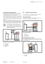
For earthed control voltage distributors, the earth potential is
the reference point for all signals between the maxGUARD
station and the control board.
To this end, the minus output of the power supply is con-
nected to a protective earth conductor terminal via a PE con-
ductor. The GND output of the maxGUARD station and the
ground connector of the control board are also connected to
the earth potential.
+24 V
GND
1
2
3
4
+24 V
0 V
Example of an earthed control voltage distributor
1
Power supply unit
2
Feed-in module
3
maxGUARD station
4
Control board


