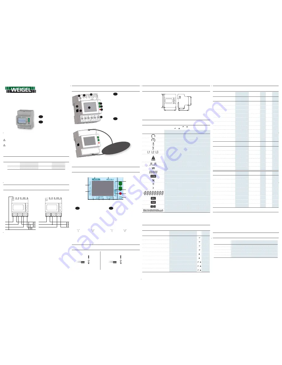
ACHTUNG!
Die Installation und Inbetriebnahme des Zählers darf nur von ausgebildeten Fachkräften durchgeführt werden. Vor jeder
Tätigkeit am Gerät muß die Versorgung getrennt werden.
WARNING!
Device installation and use must be carried out only by qualified staff.
Switch off the voltage before device installation.
VERFÜGBARE AUSFÜHRUNGEN
AVAILABLE MODELS
Modell
Model
Spannungsbereich
Voltage
Frequenzbereich
Frequency
MID Eichung
MID certified
WEZ 80-3
3x400 V
50 Hz
WEZ 80-4
3x230/400 V
In allen Modellen dürfen die Teilzähler rückgesetzt werden.
In all device models, partial counters are resettable.
ANSCHLUßBILDER
WIRING DIAGRAMS
3 PHASEN - 4 LEITER
3 PHASEN - 3 LEITER
3 PHASES - 4 WIRES
3 PHASES - 3 WIRES
Tariff
S0-2
S0-1
L1
L2
L3
N
1 2 3 4 5 6
A-V A
<
L1 <
A-V A A-V A
<
L2 <
<
L3 <
N
Tariff
S0-2
S0-1
L1
L2
L3
1 2 3 4 5 6
A-V A
<
L1 <
V
A-V A
<
L2 <
<
L3 <
Der Zähler funktionniert einwandfrei auch nur mit einer angeschlossenen Phase. Mit diesem Anschluss wird die
Hintergrundbeleuchtung zum Energiesparen ausgeschaltet.
The counter works properly even if only one phase is connected. In this wiring the backlight is disabled for energy saving
reasons.
MESSUNGEN
MEASUREMENTS
SYMBOL
SYMBOL
MESSEINHEIT
MEASURE UNIT
ANZEIGE
DISPLAY
COM PORT
COM PORT
S0 AUSGANG
S0 OUTPUT
ECHTZEITWERTE
INSTANTANEOUS VALUES
Spannung (Phase-Phase)
Voltage
V
∑
- V
L1-N
- V
L2-N
- V
L3-N
V
Außenleiterspannung (Phase-0)
Line voltage
V
L1-L2
- V
L2-L3
- V
L3-L1
V
Strom
Current
I
∑
- I
1
- I
2
- I
3
- I
N
A
Leistungsfaktor
Power factor
PF
∑
- PF
L1
- PF
L2
- PF
L3
Scheinleistung
Apparent power
S
∑
- S
L1
- S
L2
- S
L3
kVA
Wirkleistung
Active power
P
∑
- P
L1
- P
L2
- P
L3
kW
Blindleistung
Reactive power
Q
∑
- Q
L1
- Q
L2
- Q
L3
kvar
Frequenz
Frequency
f
Hz
Phasenfolge
Phase sequence
CW/CCW
Leistungrichtung
Power direction
IMP/EXP
GESPEICHERTEN ANGABEN
RECORDED DATA
Gesamtwirkenergie
Total active energy
∑
- L1 - L2 - L3
kWh
(
∑
)
Gesamtblindenergie ind. und kap.
Total ind. and cap. reactive energy
∑
- L1 - L2 - L3
kvarh
(
∑
)
Gesamtscheinenergie ind. und kap.
Total ind. and cap. apparent energy
∑
- L1 - L2 - L3
kVAh
(
∑
)
Energizähler Tarif T1/T2
T1/T2 tariff energy counters
∑
kWh, kvarh, kVAh
Rücksetzbare Energieteilzähler
Resettable partial energy counters
∑
kWh, kvarh, kVAh
Energiebilanz
Energy balance
∑
kWh, kvarh, kVAh
WEITERE ANGABEN
OTHER INFORMATION
SYMBOL
SYMBOL
WERT/STAND
VALUE/STATUS
ANZEIGE
DISPLAY
COM PORT
COM PORT
Aktuelle Tariff
Present tariff
T
1/2
Spannung über / unter der Grenze
Undervoltage/overvoltage
VOL, VUL
ON/OFF
Strom über / unter der Grenze
Undercurrent/overcurrent
IOL, IUL
ON/OFF
Frequenz über / unter der Grenze
Underfrequency/overfrequency
fOL, fUL
ON/OFF
Teilzähler
Partial counters
PAR
START/STOP
Laufende Kommunikation
Active communication
COM
ON/OFF
Laufende S0 Impulse
Active S0 pulse
S0-1, S0-2
ON/OFF
Fehlerstand
Error condition
ERR
01/02
BEDEUTUNG
= STANDARD
= BIDIREKTIONALWERT
LEGEND
= STANDARD
= BIDIRECTIONAL VALUE
In der S0 Spalte sind alle Systemwerte (
∑
) gelistet, die bei den “S0 AUSGäNGE” wählbar sind. Es ist nicht möglich, das selbe
Zähler für beide Ausgänge auszuwählen.
ANMERKUNG: bei einer 3 Leiter Ausührung werden die Werte der Ph-N Spannungen, der Neutralstrom, der
Phasenleistungen, der Phasenleistungsfaktor und aller Zählerstände nicht angezeigt.
All the system counters (
∑
) programmable for S0 outputs are shown in “SO OUTPUT” column. It is not allowed to set the
same counter for both outputs.
NOTE: in case of 3 wires model, phase-neutral voltages, neutral current, phase powers, phase power factors parameters
and all phase counters are not available.
BILANZZÄHLERWERTE BERECHNUNG
BALANCE COUNTER VALUES CALCULATION
BILANZZÄHLER
BALANCE COUNTER
FORMEL
FORMULA
kWh
(>kWh T1) – (<kWh T1) + (>kWh T2) – (<kWh T2)
kVAh ind
(>kVAh ind T1) – (<kVAh ind T1) + (>kVAh ind T2) – (<kVAh ind T2)
kVAh cap
(>kVAh cap T1) – (<kVAh cap T1) + (>kVAh cap T2) – (<kVAh cap T2)
kvarh ind
(>kvarh ind T1) – (<kvarh ind T1) + (>kvarh ind T2) – (<kvarh ind T2)
kvarh cap
(>kvarh cap T1) – (<kvarh cap T1) + (>kvarh cap T2) – (<kvarh cap T2)
ÜBERSICHT
OVERVIEW
D
DEUTSCH
Neutralklemme (nur für 4-Leiter Modell)
1.
Klemme für Tarifeingang
2.
S0 Ausgangsklemme
3.
UP Taste
4.
ENTER Taste
5.
Messtechnische LED
6.
Strom- und Spannungsklemmen
7.
Sicherheitsaufkleber
8.
(DARF NICHT ENTFERNT WERDEN)
Infrarot-Schnittstelle
9.
LCD Display Hintergrundbeleuchtung
10.
GB
ENGLISH
Neutral terminal (only for 4 wire models)
1.
Tariff input terminals
2.
Terminals for the two S0 outputs
3.
UP key
4.
ENTER key
5.
Metrological LED
6.
Current and voltage terminals
7.
Safety-sealing (DO NOT REMOVE)
8.
Optical COM port
9.
Backlight LCD display
10.
PLOMBIERBARE
KLEMMENABDECKUNG
!
SEALABLE
TERMINAL
COVERS
!
10
9
8
7
6
5
4
3
2
1
SYMBOLE AUF FRONTSEITE (BEISPIELE)
SYMBOLS ON FRONT PANEL (EXAMPLE)
D
DEUTSCH
Firmenlogo
A.
Gerätenamen
B.
Seriennummer
C.
Data Matrix
D.
Schutzart
E.
Integrationskonstante (Messtechnische LED)
F.
Grundstromwert (Max Strom)
G.
Arbeitstemperaturbereich
H.
Genauigkeitsklasse
I.
Spannung-/Frequenznominalwert
J.
Anschlußbild
K.
=Dreiphasig 4 Leiter,
=Dreiphasig 3 Leiter
MID Eichung Symbol
L.
Homologationsnummer
M.
GB
ENGLISH
Company logo
A.
Device name
B.
Serial number
C.
Data Matrix
D.
Protection class
E.
Meter constant (Metrological LED)
F.
Base current (max current)
G.
Working temperature
H.
Accuracy class
I.
Nominal voltage/frequency
J.
Wiring type
K.
=3phase 4 wires,
= 3phase 3 wires
MID approval symbols
L.
Type approval certification
M.
C
D
E
F
A
B
K
J
I
H G
M
L
KABEL-ABISOLIERLÄNGE
CABLE STRIPPING LENGTH
Verdrahtung an den Messeingängen (A & V)
Connection measuring terminals (A & V)
Verdrahtung an S0 / Tarif Klemmen
S0 output / tariff terminals connection
5 mm
0,5 Nm
15 mm
2 Nm
PZ2 Schraubendreher anwenden
Use a PZ2 screwdriver
Ein 0,8x3,5 mm Flachschraubendreher anwenden
Use a blade screwdriver with 0.8x3.5 mm size
ABMESSUNGEN (mm)
SIZE (mm)
90
72
65
44
45
ANZEIGENSYMBOLE
SYMBOLS ON DISPLAY
Der Displaytest erfolgt durch gleichzeitiges Drücken der Tasten
und für 10 s.
Display test can be carried out by pressing for 10 s
and simultaneously.
SYMBOL
SYMBOL
BESCHREIBUNG
DESCRIPTION
Richtige Phasenfolge (123)
Correct phase sequence (123)
Falsche Phasenfolge (132)
Wrong phase sequence (132)
Undefinierte Phasenfolge (z.B. eine oder zwei Phasen fehlen)
Undefined phase sequence (i.e. one or two phases are missing)
Systemwerte
System value
Phasenwert
Value phase number
Beschädigten metrologischen Parameter (auf dem Hauptanzeigefeld wird Code: XX
angezeigt). Der Zähler ist unnutzbar und soll sofort an der Hersteller retouriert werden.
Metrological parameters corrupted (Code: XX will be displayed in the main area).
The counter cannot be used and it must be returned to the Manufacturer.
Nummer des aktiven S0 Ausgangs
Active S0 output number
Bezogener (>), gelieferter (<) Leistungs- oder Energiewert
Imported (>), exported (<) power or energy value
Identifiziert die Einstell- (SETUP) oder Info (INFO) Seiten
Identify the Setup page (SETUP) or the Info page (INFO)
Laufende Kommunikation
Communication ON status
Einstellseite
SETUP page
Kapazitiv- /Induktivwert
Capacitive / inductive value
Hauptanzeigefeld
Main area
Symmetrischer Zählerwert
Balance counter value
Teilzählerwerte. Wenn blinkend ist der Zähler gestoppt.
Partial counter value. If flashing, the counter is stopped.
Zählerwert der Tarif 1 oder 2
1 or 2 tariff counter value
Messeinheitsfeld
Measuring unit area
TASTENFUNKTIONEN
KEY FUNCTIONS
FUNKTION
HOW TO
WO
WHERE
TASTE
KEY
WIE LANGE
PRESS TIME
Gruppe blättern
Scroll loops
Jede Seite außer der Einstellung
Any page except for Setup
Sofort
Instantaneous
Zugang zu den Einstellseiten
Access Setup pages
“Setup?” Seite
“Setup?” page
›3 s
Bestätigung eines Wertes / Anzahl
Confirm a value/digit
Einstellseite
Setup pages
Sofort
Instantaneous
Ausgang aus der Einstellseiten
Exit Setup pages
Einstellseiten
Setup pages
›3 s
Die Seiten einer Gruppe blättern
Scroll pages in a loop
Jede Seite einer Gruppe
Any loops page
Sofort
Instantaneous
Einen Wert ändern
Change a value/digit
Einstellseite
Setup pages
Sofort
Instantaneous
Den angezeigten Teilzähler starten / sperren
Start/stop the displayed partial counter
Teilzählerseiten
Partial counters pages
+
Sofort
Instantaneous
Den angezeigten Teilzähler rücksetzen
Reset the displayed partial counter value
Teilzählerseiten
Partial counters pages
+
›3 s
Displaytest
Display test
Jede Seite außer der Einstellung
Any page except for Setup
+
›10 s
WEZ 80-3
WEZ 80-4
80A Dreiphasiger Energiezähler -
80A three phase energy counter
D
- BEDIENUNGSANLEITUNG
GB
- USER MANUAL
1MW
OEC80T001
Der
Inhalt
dieser
Anl
eitung
und
die
technischen
Spezifikationen
können
oh
ne
v
or
he
ri
ge
A
nk
ün
di
gu
ng
g
eä
nd
er
t
w
er
de
n.
D
ie
B
es
ch
re
ib
un
g
de
r
Pr
oduktspezifikation s
tellt k
einen V
ertr
agsbes
tandt
eil dar
.
The
cont
ent
and
the
technic
al
specific
ation
of
this
User
Manual
ar
e
subject
to
change without prior notic
e. The
y do not r
epr
esent any c
ontr
actual obligation.
Weigel Meßgeräte GmbH
Erlenstraße 14 • 90441 Nürnberg • GERMANY
Tel. : +49 (0)911 / 4 23 47 - 0 • Fax : +49 (0)911 / 4 23 47 - 39
info@weigel-messgeraete.de • www.weigel-messgeraete.de


