ACHTUNG!
Die Installation und Inbetriebnahme des Moduls darf nur von ausgebildeten
Fachkräften durchgeführt werden. Vor jeder Tätigkeit am Gerät muß die
Versorgungsspannung getrennt werden.
WARNING!
Device installation and use must be carried out only by qualified staff.
Switch off the voltage before device installation.
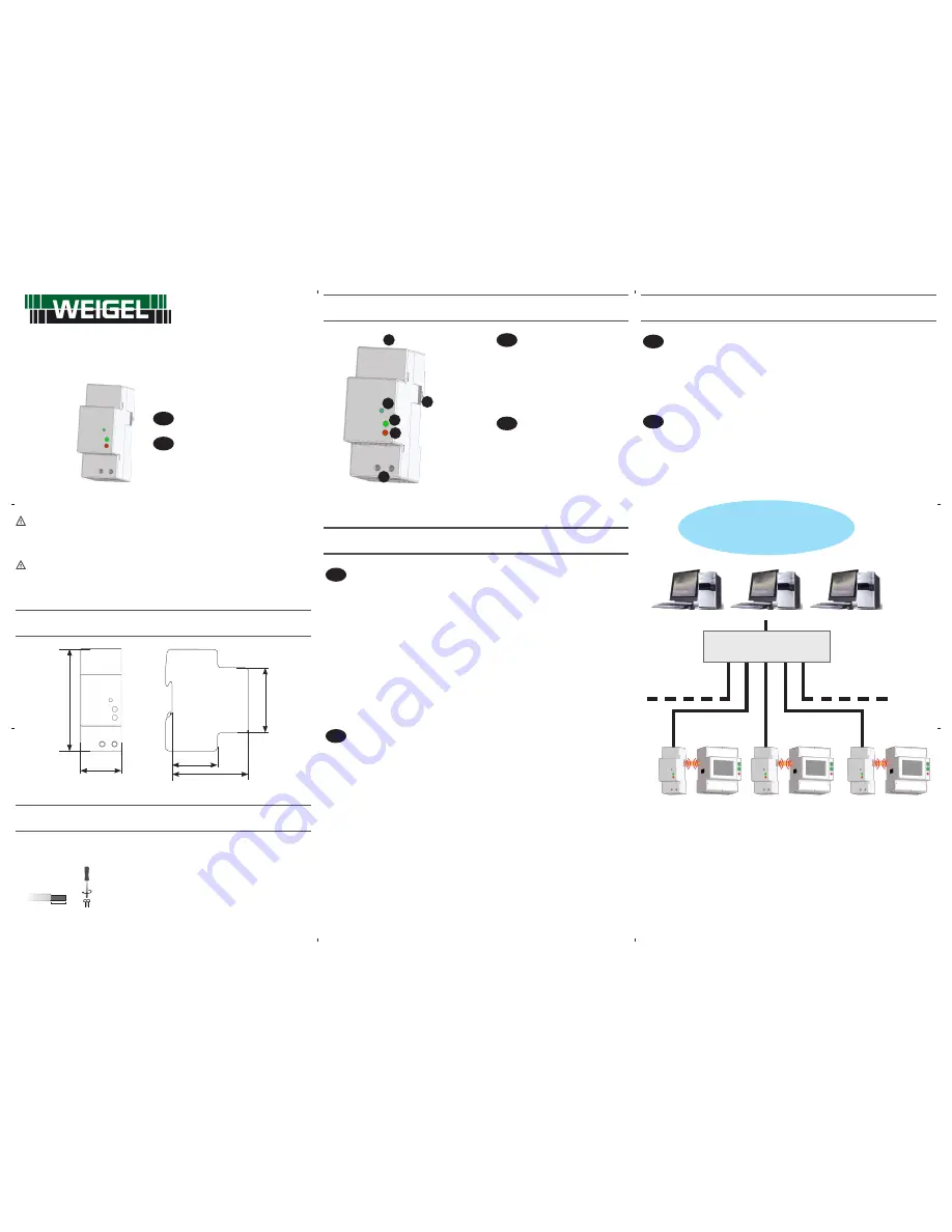
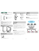
ABMESSUNGEN (mm)
SIZE (mm)
90
36
65
44
45
KABElABISolIERTE läNGE
CABlE STRIPPING lENGTH
Verdrahtung an den Klemmen
Terminals connection
5 mm
0,5 Nm
Benutzen Sie einen 0,8x3,5 mm großen Flachschraubendreher
Use a blade screwdriver with 0.8x3.5 mm size
ÜBERSICHT
oVERVIEW
D
DEUTSCH
LAN Schnittstelle
1.
Infrarot-Schnittstelle
2.
Taste WERKSEINSTELLUNG
3.
LED Zustand
4.
LED Linkaktivität
5.
Hilfsspannungsklemmen
6.
GB
ENGLISH
LAN port
1.
Optical COM port
2.
SET DEFAULT key
3.
Status LED
4.
Link activity LED
5.
Power supply terminals
6.
3
4
5
6
2
1
ERSTE SCHRITTE
GETTING STARTED
D
DEUTSCH
Schließen Sie das LAN GATEWAY Modul an dem Netzswitch oder am PC an und schalten Sie es ein.
1.
Überprüfen Sie die am PC eingestellte IP Adresse: falls sie anders als
2.
192.168.1.xxx lautet, ändern
Sie diese (z.B. die richtige IP Adresse wäre: 192.168.1.1).
Starten Sie den Internet Browser (z.B. Internet Explorer, Mozilla Firefox) und schreiben Sie in das
3.
Adressfeld 192.168.1.253 (Werkseinstellung des LAN GATEWAY).
Loggen Sie sich zum LAN GATEWAY als Administrator ein (die LOGIN Angaben sind Benutzername:
4.
admin, Passwort: admin).
Stellen Sie auf der Parametrierseite des Webservers (
5.
Settings) die gewünschten LAN Parameter
ein (IP Adresse, Subnet Mask, usw.). Für weitere Angaben steht ihnen auf der beiliegenden CD eine
ausführiliche Bedienungsanleitung des Webservers zur Verfügung.
Falls notwending, setzen Sie die Einstellungen an der LAN Schnittstelle des PC auf die
6.
ursprünglichen Werte zurück.
GB
ENGLISH
Connect the LAN GATEWAY to the network switch or directly to the PC and power it on.
1.
Check the IP address class set for PC LAN interface: if different from
2.
192.168.1.xxx, change it (e.g.
correct IP address: 192.168.1.1).
Run the Internet browser (e.g. Internet Explorer, Mozilla Firefox) and type in the web address field
3.
192.168.1.253 (LAN GATEWAY default address).
Access LAN GATEWAY web server as Administrator, entering the proper username and password
4.
(Username: admin, Password: admin).
In web server
5.
Settings page, set the desired LAN parameters (IP address, subnet mask, ...). For
further details, refer to the web server user manual available on the enclosed CD.
If needed, restore the previous settings on the PC LAN interface.
6.
VERDRAHTUNG
CoNNECTIoNS
D
DEUTSCH
Nachdem die Anschlüsse am ETHERNET Netzwerk durchgeführt worden sind, koppeln Sie
jedes LAN GATEWAY Modul mit einem Zähler. Positionieren Sie diese exakt in einer Linie
nebeneinander, so daß der optische Anschluss des Moduls dem des Zählers gegenübersteht.
Stellen Sie dann Netzanschluss her.
GB
ENGLISH
After making ETHERNET connections, combine each LAN GATEWAY module with a single counter:
place them side by side, perfectly lined up, with module optical port facing the counter optical
port. Then, carry out power supply connections.
ETHERNET
SWITCH
lAN NETZWERK
lAN NETWoRK
WEZ Ethernet
LAN GATEWAY Kommunikationsmodul -
LAN GATEWAY communication module
D
- BEDIENUNGSANLEITUNG
GB
- USER MANUAL
D
er
In
ha
lt
di
es
er
A
nl
ei
tu
ng
u
nd
d
ie
te
ch
ni
sc
he
n
Sp
ez
ifi
ka
tio
ne
n
kö
nn
en
oh
ne
vo
rh
er
ig
e
A
nk
ün
di
gu
ng
g
eä
nd
er
t w
er
de
n.
D
ie
B
es
ch
re
ib
un
g
de
r
Produktspezifikation stellt keinen Vertragsbestandteil dar.
The
content
and
the
technical
specification
of
this
User
Manual
are
subject
to
change
without
prior
notice.
They
do
not
represent
any
contractual obligation.
1MW
OECLAN001
Weigel Meßgeräte GmbH
Erlenstraße 14 • 90441 Nürnberg • GERMANY
Tel. : +49 (0)911 / 4 23 47 - 0 • Fax : +49 (0)911 / 4 23 47 - 39
info@weigel-messgeraete.de • www.weigel-messgeraete.de


