background image

109

Videoplayer Configuration

15.1.2  Videos (Tab)

Add Videos

To add a video click "Add Videos" and choose your videos.


Summary of Contents for ProCommander LTC

Page 1: ...Weigl ProCommander LTC Instruction Manual...

Page 2: ...48 www WeiglControl com Info WeiglControl com Weigl Control except Americas Weigl Works LLC 1 440 941 5849 www WeiglControls com Info WeiglControls com Weigl Control Americas ProCommander LTC Version...

Page 3: ...ONT 17 3 2 ProCommander LTC REAR 21 3 2 1 Pin assignment for Open Collector Circuit 21 4 USB driver installation 29 5 Modification of the menu of ProCommander LTC 33 5 1 ProCommander Series 34 5 2 Men...

Page 4: ...gger three shows 78 9 2 3 Project 3 Three shows alternate in an interval of 90 minutes between 8 a m in the morning till 2 a m in the night 80 9 2 4 Project 4 One area has to be filled with four diffe...

Page 5: ...eos Tab 109 15 1 3 Playlist Tab 110 15 1 4 Player Tab 111 15 2 Show programming Software Conductor 113 15 2 1 Layout Tab 113 15 2 2 Timeline Tab 115 15 2 3 Deployment Tab 116 16 Appendix 119 16 1 Meas...

Page 6: ......

Page 7: ...ll risk of the customer Weigl assumes no liability for applications assistance customer produced design software performance or infringements of patents or copyrights Weigl does not warrant or represe...

Page 8: ...he ProCommander LTC must not exceed the maximum allowable voltage 12V and must be protected accordingly In addition correct polarity must be utilized to avoid damage to the ProCommander LTC Failure to...

Page 9: ...ATTENTION Damages caused by improper handling improper wiring or improper use will void warranty and Weigl GmbH Co KG or Weigl Works LLC cannot be held liable ATTENTION With the removal of the label o...

Page 10: ...sonable protection against harmful interference in a residential installation This equipment generates uses and can radiate radio frequency energy and if not installed and used in accordance with the...

Page 11: ...ult in interference to radio and TV reception The user is cautioned that changes and modifications made to the equipment without the approval of manufacturer could void the user s authority to operate...

Page 12: ...mberg 3 4201 Gramastetten Austria US Importer s Name Weigl Works LLC Importer s Address 441 W Bagley Rd 177 Berea OH 44107 Type of Equipment Entertainment and Lighting Control Equipment Class Commerci...

Page 13: ...For the evaluation regarding EMC the following standards were applied EN 61000 6 2 2005 Electromagnetic compatibility EMC Part 6 2 Generic standards Immunity for industrial environments EN 61000 6 4...

Page 14: ...surement This device complies with Part 15 of the FCC Rules Class B Itheundersigned herebydeclarethattheequipmentspecified above conforms to the above directive s and standard s Place Gramastetten Dat...

Page 15: ...he warranty will still expire 24 months from the original date of purchase Damaged parts will not be returned Any further legal claims in particular those for compensation for direct or indirect damag...

Page 16: ...the device by persons not expressly authorized by Weigl GmbH Co KG or Weigl Works LLC to do so Failure to follow the instructions i e connection to the wrong voltage or incorrect input or output circ...

Page 17: ...TXD 7 PS DC24V max 50mA 8 GND RS232 2 NET OUT 1 RS485 2 2 RS485 2 3 RS232 2 TXD 4 RS485 1 WEM NET 5 RS485 1 WEM NET 6 RS232 2 RXD 7 PS DC24V max 50mA 8 GND RS232 1 shares RS485 1 RS232 2 shares RS485...

Page 18: ...m advanced DFU firmware updates to the ProCommander LTC Please make sure that you have installed the applicable driver for RS 232 support to use the USB port in conjunction with either the Weigl Hardw...

Page 19: ...nism for easy removal ATTENTION Please ensure that you do not press too hard on the card otherwise the ejection mechanism can be destroyed When the card is valid Card Connected will be shown in the di...

Page 20: ...nded pressing the joystick more than 3 seconds After 3 seconds End Show will be displayed By a further confirmation with Enter the show is cancelled The volume of the show can be changed directly with...

Page 21: ...K R2 10K R1 D1 ZP D5V1 2 1 1 1 1 2 2 2 TO_IN1 8 INPUT CIRCUIT IN1 IN8 ALWAYS MOUNT FLYBACK DIODE IN REVERSE DIRECTION PARALLEL TO EACH INDUCTIVE LOAD PS 12V 3A PS GND DMX UNIVERSE 1 RS232 RS232 IN 1 I...

Page 22: ...ander LTC has a bidirectional DMX port It outputs full Universe with 512 channels Simultaneously via the pins 4 and 5 an external DMX signal can be connected With the integrated merge function a part...

Page 23: ...inputs can be defined in the Control ini file See chapter Control ini for more information OPEN COLLECTOR 1 8 9 16 The ProCommander LTC has 16 open collector outputs Outputs 1 8 are standard open coll...

Page 24: ...S FramesPerSecond 25FPS and 30FPS SMPTE timecode frame rates are controlled within the software you are using to build your show ie VenueMagic SC or Conductor During show programming this information...

Page 25: ...via the use of ASCII commands such as rtc1 and rtc0 Complete SMPTE operational commands are found pre scripted in the drop down menu structure of VenueMagic SC as well as in the ASCII chart RS232 3 8...

Page 26: ...o the right channel Pin 1 is common ground Supply and GND Pins Schematic for output connection At each Pin 5 of the 6 pole connector block the supply voltage of the power supply is brought out if the...

Page 27: ...27 Pin assignment ProCommander LTC Jumper open Jumper closed...

Page 28: ...losed and the power supply of the ProCommander LTC is used for the operation of the connected components it is important to make sure that the maximum total current must not exceed 500mA Pin 6 of the...

Page 29: ...ander LTC is connected to your computer Windows automatically search for the appropriate driver software When you see this dialog box select Browse my computer for driver software Click on Browse and...

Page 30: ...his driver software anyway Microsoft Windows 8 may require that you turn off during signing in the setup configuration for your computer Please refer to documentation included with your operating syst...

Page 31: ...31 USB driver installation...

Page 32: ...32 USB driver installation If you later want to elicit the COM port you will find this under Control Panel Device Manager Ports COM LPT...

Page 33: ...different LEVELS As you venture deeper into the menu structure the higher the number of the respective LEVELS Through movement of the joystick to the left right up or down different menu items can be...

Page 34: ...er resolution please download the menu plan from Weigl and Solutions Center LEVEL 1 is active as soon as ProCom is displayed If you move the Joystick once down the next function is displayed in this c...

Page 35: ...volume now you are on LEVEL 2 As soon as the requested value is displayed confirm with Enter within 2 seconds If no confirmation is received while the volume is set the next time the previously stored...

Page 36: ...value Based on LEVEL 2 you will be forwarded on LEVEL 3 by confirmation with Enter LEVEL 3 locate under MainSetup following functions Set IP Adrs Set Port and Set Factory Set IP Adrs With the functio...

Page 37: ...o the LEVEL 4 of the menu plan The second line of the display shows the current value and corresponds with LEVEL 5 of the menu plan For example you want to change the value of port 3 you have to move...

Page 38: ...the ProCommander LTC Therefore you have to activate Set Factory by pressing Enter You will be automatically forwarded to LEVEL 4 of the menu plan If you confirm Set Factory with Enter the ProCommande...

Page 39: ...ime LTC TimeOut Configure Menu MENU ProCommander LTC Configure LEVEL 2 LEVEL 3 LEVEL 4 LEVEL 5 Left Back one level up Enter Press the button to select the displayed function or store value Menu ON OFF...

Page 40: ...L 4 of the menu plan The second line of the display shows the current value and corresponds to LEVEL 5 of the menu plan The asterisk next to the value indicates that it is currently active You can cho...

Page 41: ...nds Move the joystick up or down to set the requested value If it appears on the display confirm the value by pressing Enter Once the value is saved an asterisk will be displayed By moving the joystic...

Page 42: ...The second line of the display shows the current value and corresponds to LEVEL 5 of the menu plan The asterisk next to the value indicates that it is currently active You can choose between the driv...

Page 43: ...menu plan The asterisk next to the value indicates that it is currently active You can choose between the two functions ON and OFF You must move the joystick either up or down If the desired function...

Page 44: ...you will be forwarded on LEVEL 3 by confirmation with Enter LEVEL 3 locate under Audio following functions Volume Bass and Treble Volume With the function Volume you can change the volume of the left...

Page 45: ...ht channel For this purpose you have to activate Bass with Enter In the first line of the display Set Bass appears this corresponds to the LEVEL 4 of the menu plan The second line of the display shows...

Page 46: ...alue and corresponds to LEVEL 5 of the menu plan The asterisk next to the value indicates that it is currently active You can choose between the values of 8 to 7 the value 8 minus eight corresponds wi...

Page 47: ...L 2 LEVEL 3 LEVEL 4 LEVEL 5 Left Back one level up Enter Press the button to select the displayed function or store value Based on LEVEL 2 you will be forwarded on LEVEL 3 by confirmation with Enter L...

Page 48: ...is corresponds to the LEVEL 4 of the menu plan The second line of the display shows the current value and corresponds to LEVEL 5 of the menu plan The asterisk next to the value indicates that it is cu...

Page 49: ...u can choose between the values of 0 to 59 You must move the joystick either up or down to set the requested value If the value appears on the display confirm it by pressing Enter Once the value is sa...

Page 50: ...first line of the display Set Day appears this corresponds to the LEVEL 4 of the menu plan The second line of the display shows the current value and corresponds to LEVEL 5 of the menu plan The asteri...

Page 51: ...stick to the left you can return to a parent LEVEL Year With the function Year you can define the year of the intern real time clock of the ProCommander LTC You have to activate Year by pressing Enter...

Page 52: ...00 V0 00 LEVEL 5 Left Back one level up Enter Press the button to select the displayed function or store value Based on LEVEL 2 you will be forwarded on LEVEL 3 by confirmation with Enter LEVEL 3 loca...

Page 53: ...53 Modification of the menu of ProCommander LTC IP Address Here the current IP address of the device will be displayed Port Here the current values of the ports can be controlled...

Page 54: ...54 Modification of the menu of ProCommander LTC...

Page 55: ...u connect it to Further information you find under USB driver installation Now that you have started your terminal program and chosen the activated COM port you can request the current settings with t...

Page 56: ...uble click After starting this window appears Press the button Scan Devices and the connected device will be found automatically By clicking on the listed device the current settings will be listed No...

Page 57: ...rk you have to be aware that the IP address of the computer in combination with the subnet mask matches with the factory settings of the ProCommander LTC The factory setting of the IP address is 10 0...

Page 58: ...e changes you can use the configurator on a network connection and also make appropriate setting changes on the ProCommander LTC Alternatively you can use the front display menu or USB to change these...

Page 59: ...choose the new ProComLTC_Vxxx hex file The data Vxxx corresponds to the latest version of the ProComLTC hex file This will be transferred to the ProCommander LTC ATTENTION During this process do not...

Page 60: ...nder LTC ATTENTION This operation is ONLY available over network and not via USB or serial connection Please turn of Wi Fi and any other connections during the update process to avoid potentially crip...

Page 61: ...visual method of updating the firmware at this time Please see additional information regarding the USB firmware restore process for additional information Meanwhile you can see on the display of the...

Page 62: ...the computer If you are asked to install a driver then choose the usb USBRS232driver folder which you will find in your new folder where you have unzipped the attached files After the installation ru...

Page 63: ...ll stay blank don t worry you are asked for installing another driver Now choose the C Program Files Atmel Flip 3 4 3 usb folder where the atmel_usb_dfu inf driver is located which will be needed for...

Page 64: ...ot be opened but after a few seconds you should get this window Once both drivers are installed all further ProCommander updates can be done immediately through the USB interface You are simply asked...

Page 65: ...X input can be used to capture incoming DMX data to the timeline of either ConductorTM or VenueMagic SC 7 1 Merge function An external DMX signal can be integrated into the internal DMX signal through...

Page 66: ...the sum will be transferred into the output signal The output value will be limited to the maximum value 225 Merge Combine Within the merge range only the external signal will be transferred to the o...

Page 67: ...RAM variables and EEProm variables The RAM variables are only valid during the runtime of the device and lose their content after power off After power up they are set to the value 0 The EEProm variab...

Page 68: ...68 Variable...

Page 69: ...or toggle event every level change at an input With toggle both the press and the release of a key action will cause a trigger event If the device has resources to process the commands all functions...

Page 70: ...of several trigger events you have to do this via variables 9 1 1 i Input events Event related to the remote inputs 1 16 Example i1c if input 1 is activated c close then the downstream command will b...

Page 71: ...ertion of the card the time is set to zero means modulo which means that any time the value is reached the command is executed Example tm01 20 if the time 1 minute 20 seconds is reached after the star...

Page 72: ...lue range 1 12 y year value range 12 11 corresponds 2012 to 2111 h hour value range 0 23 m minute value range 0 59 s seconds value range 0 59 As operators are permitted whereby modulo means The order...

Page 73: ...that the command will be executed the next time it becomes true again For example the condition rc s 1 would be executed only once because second modulo 1 is always true 9 1 4 v Variable events For b...

Page 74: ...ollector outputs 1 and 4 will be activated and additionally the DMX channel 10 will be set to 255 9 1 5 d DMX events The whole DMX univers can also be used as a start condition for a command As operat...

Page 75: ...ontrol ini looks like this i1c rsn1 i2c rsn2 The content of the Control ini file can look like this i1c ess1001 i6c edv10 255 i2c esd3 Hello World i3o epf1 20 2 5 i4t epl1_4 50 i5c cfm0 5 i5o cfm32 5...

Page 76: ...value which is stored in EE Prom cfm32 5 8th line At 1 minute and 20 seconds after switching on the device or after insertion of the microSD card tm01 20 the first show starts in normal mode rsn SHOW...

Page 77: ...ike this tm00 00 rsnl1 t 45 00 vcc1 1 rst2 1st line At time 00 00 right after power up of the device or insertion of the memory card tm00 00 the first show 001_ SHOW WM1 will start in loop mode rsnl1...

Page 78: ...three shows and is triggered with three switches The first show should start if switch 1 and 3 are closed and switch 2 is open The seconds show should start if switch 1 and 2 are closed and switch 3 i...

Page 79: ...1 vmc3 1 6th line If input 3 is open i3o then the value of variable 3 will attain 0 vmc3 0 7th line If variable 1 gets the value 1 vcc1 1 the variable 2 the value 0 vcc2 0 and the variable 3 the valu...

Page 80: ...sharp the second show at 8 30 a m and the third show at 9 a m sharp Afterwards the first show starts at 9 30 a m again The procedure will be continued till 2 a m sharp of the following day The conten...

Page 81: ...till 2 00 a m 6th line At every half hour if the hour is less than 2 a m rc h 2 m 30 variable 2 will be incremented by one vmc2 1 This covers the time span from 0 30 a m till 1 30 a m 7th line If the...

Page 82: ...82 Control ini 10th line As soon as the value of variable 2 attains 3 vcc2 3 the variable 2 will be cleared to zero vmc2 0 and the cycle 1 2 3 for variable 2 starts again...

Page 83: ...the rotary switch are assigned to pin 10 13 The content of the Control ini file looks like this i10c vmc1 1 i11c vmc1 2 i12c vmc1 3 i13c vmc1 0 i1c vcc1 1 rsn1 i1c vcc1 2 rsn2 i1c vcc1 3 rsn3 i1c vcc1...

Page 84: ...en the seventh show 002_SHOW WM1 will start rsn2 In this case the show for the first area is in Spanish 7th line If input 1 is activated i1c and the value of variable 1 is equal 3 vcc1 3 then the thir...

Page 85: ...is started via the third DMX channel The content of the Control ini file looks like this d2 5 rsn1 d1 10 rsn2 d3 20 rsn3 1st line If the value of DMX channel 2 is equal 5 d2 5 then show 1 001_SHOW WM1...

Page 86: ...inated similar to a VU meter display If the button isn t activated the variable will be decremented by the variable commands in the show and the LEDs turn off The content of the Control ini file looks...

Page 87: ...alue of variable 1 is equal 3 vcc1 3 then the output 1 to 3 will be activated and output 4 to 6 will be cleared ess111000 7th line If the value of variable 1 is equal 4 vcc1 4 then the output 1 to 4 w...

Page 88: ...and channel in the second show At time zero the command cfm0 2 The volume of the audio fades within two second to 0 has to be included At time two seconds the command rse1 has to be included that the...

Page 89: ...closed i1c then show 1 001_SHOW WM1 will start in normal mode rsn1 2nd line If input 2 is closed i2c then show 2 002_SHOW WM1 will start in add mode rsa2 Because of the commands within the show the f...

Page 90: ...of the first show vmc1 1 at the end of the second show vmc1 2 at the end of the third show and so on The content of the Control ini file looks like this i1c vcc1 0 rst1 i1c vcc1 1 rst2 i1c vcc1 2 rst3...

Page 91: ...closed i1c and the value of variable 1 is equal 4 vcc1 4 then the first show 005_SHOW WM1 will start in restart mode rst5 6th line If the value of variable 1 is equal 4 vcc1 4 then variable 1 will at...

Page 92: ...92 Control ini...

Page 93: ...ly generate OGG Vorbis files ATTENTION It depends on the software edition of Conductor if you can export an audio file in AAC The ProCommander LTC can manage multiple playlists The playlists are store...

Page 94: ...will end the playing of the playlist at the end of the current track pst audio Track001 ogg is the command to play a single track from a particular folder If a track is already playing the volume fade...

Page 95: ...be WM1 Example 001_SHOW WM1 023_TEST WM1 320_PLAY WM1 By using this order remote access to the shows can be done very easily just by number This can be used for starting shows within a show as well a...

Page 96: ...p of audio files have to be stored in directories named PLAYLxxx where xxx is a number between 000 and 999 The number 000 has a special function This playlist is played automatically after powering on...

Page 97: ...Programming the ProCommander LTC Due to the open interface protocol there are various software programs that support the ProCommander LTC Please refer to the manual of the respective software to lear...

Page 98: ...98 Programming the ProCommander LTC...

Page 99: ...ub Net address adjustment A1 A2 of a device each Pro I O module analyze only the own commands If it s necessary to assign individual IP addresses so that conflicts with other devices in the network ca...

Page 100: ...e Sub Device ID address 1 the IP address 192 168 10 150 is chosen The command reads as followed swi192 168 10 150 It assigns automatically IP addresses in ascending order for all 32 possible modules o...

Page 101: ...nd Pro I O In this case the result looks like this Now all IP addresses of the Pro I O modules have to be modified in accordance with the chart above So module with A1 on the display gets 192 168 10 1...

Page 102: ...r are in use different IP addresses for all devices have to be assigned for their Pro I O modules Example For the second ProCommander the first Pro I O module will be assigned with the IP address 192...

Page 103: ...d Pro I O All IP addresses of the Pro I O modules which are connected with the second ProCommander have to begin with 192 168 10 182 ATTENTION More detailed information to configure a Pro I O module c...

Page 104: ...104 Network connection between ProCommander LTC and Pro I O...

Page 105: ...ndle ASCII protocol has been introduced In addition there is an open HEX protocol designed for short commands By the very large ASCII protocol the ProCommander can also be easily integrated into the m...

Page 106: ...106 Interface protocols...

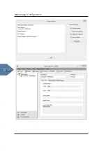
Page 107: ...on 15 1 Videoplayer Setup 15 1 1 Search for Videoplayer Connect the Player of the ProCommander LTC and the Computer via an Ethernet wire Open the program Quick Sign Pro It automatically searches for a...

Page 108: ...108 Videoplayer Configuration...

Page 109: ...109 Videoplayer Configuration 15 1 2 Videos Tab Add Videos To add a video click Add Videos and choose your videos...

Page 110: ...yer Configuration 15 1 3 Playlist Tab To create a playlist click New Playlist and add the videos The order of the videos can be changed by pressing Move Up or Move Down Afterwards confirm your playlis...

Page 111: ...Videoplayer Configuration 15 1 4 Player Tab In the Tab Player under Player Control press the button Load Play All videos will be copied to the internal storage of the video player of the ProCommander...

Page 112: ...112 Videoplayer Configuration Load Play When the upload is finished the line Load Play successful appears and confirm with OK...

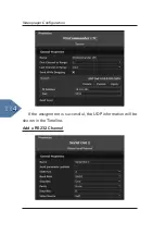
Page 113: ...NET 2 2 RXD DC24V max 50mA 1 2 1 1 8 8 1 5 6 9 1 5 6 9 Connect your computer and the ProCommander LTC via an Ethernet cable Open Conductor and add a device in the Timeline tab Activate it with a click...

Page 114: ...114 Videoplayer Configuration If the assignment is successful the UDP information will be shown in the Timeline Add a RS232 Channel...

Page 115: ...he RS232 Channel to Port 2 15 2 2 Timeline Tab ASCII commands Double click in the RS232 Channel to add a command Add the command in the section Properties into the ASCII PLAY VIDEO Weigl EM mp4 1 PLAY...

Page 116: ...l EM mp4 1 STOP PLAY VIDEO ShowControl mp4 1 STOP PLAY VIDEO ShowControl_powered_by_Weigl mp4 1 STOP ATTENTION And keep in mind to add in the HEX the expression 0D at the end of each HEX command Other...

Page 117: ...Autostart if the show should run after the card has been inserted into the micro SD slot that means without any additional trigger Activate Loop if the whole show should run in a loop Deploy your proj...

Page 118: ...118 Videoplayer Configuration...

Page 119: ...119 Appendix 16 Appendix 16 1 Measurements H 48 mm 1 57 in B 485 mm 19 09 in T 124 mm 4 88 in 1 3 kg 2 87 lb...

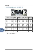
Page 120: ...N C N C N C N C N C Pin 2 RXD RXD RXD RXD RXD RXD Pin 3 TXD TXD TXD TXD TXD TXD Pin 4 N C N C N C N C N C N C Pin 5 GND GND GND GND GND GND Pin 6 N C N C N C N C N C N C Pin 7 N C N C N C N C N C N C...

Page 121: ...UDIO OUT Connector Function Pin 1 GND Pin 2 Audio Out LEFT Pin 3 Audio Out LEFT Pin 4 Audio Out RIGHT Pin 5 Audio Out RIGHT 16 4 Pin assignment DMX OUT Connector Function Pin 1 GND Pin 2 DMX OUT Pin 3...

Page 122: ...6 Input 1 8 Input 9 16 Connector Upper Row Lower Row 1 Input 1 Input 9 2 Input 2 Input 10 3 Input 3 Input 11 4 Input 4 Input 12 5 Input 5 Input 13 6 Input 6 Input 14 7 Input 7 Input 15 8 Input 8 Input...

Page 123: ...5 2 Open Collector 2 Open Collector 6 3 Open Collector 3 Open Collector 7 4 Open Collector 4 Open Collector 8 5 Common Cathode1 Common Cathode2 6 GND GND 1 If jumper K 14 is closed than Pin 5 is conne...

Page 124: ...124 Appendix...

Page 125: ...125 Glossary 17 Glossary Sub Device ID Device address Each device has its own device address it is required to issue commands which are sent to a device to be handled correctly...

Page 126: ...126 Glossary...

Page 127: ...check out our latest examples at www Weigl support Please run also a Firmware Update on your Weigl device to ensure that your device is able to interpret the latest ASCII commands Even though I ve rea...

Page 128: ...128 F A Q...

Page 129: ...2 78 Project 3 80 Project 4 83 Project 5 85 Project 6 86 Project 7 88 Project 8 90 Example 70 71 72 73 Structure of the Control ini file 70 DMX events 74 Input events 70 Real time clock events 71 Time...

Page 130: ...P Pin assignment 17 AUDIO OUT 109 DMX OUT 109 FRONT 17 Input 1 16 110 Open Collector 1 8 111 REAR 21 RS232 3 8 108 Playlist functions 93 POWER 21 Programming the ProCommander 2 97 R RealTimeClk Day 50...

Reviews: