background image

• Installation    • Start-Up    • Maintenance    • Parts

25

Part No. 550-141-935/0602

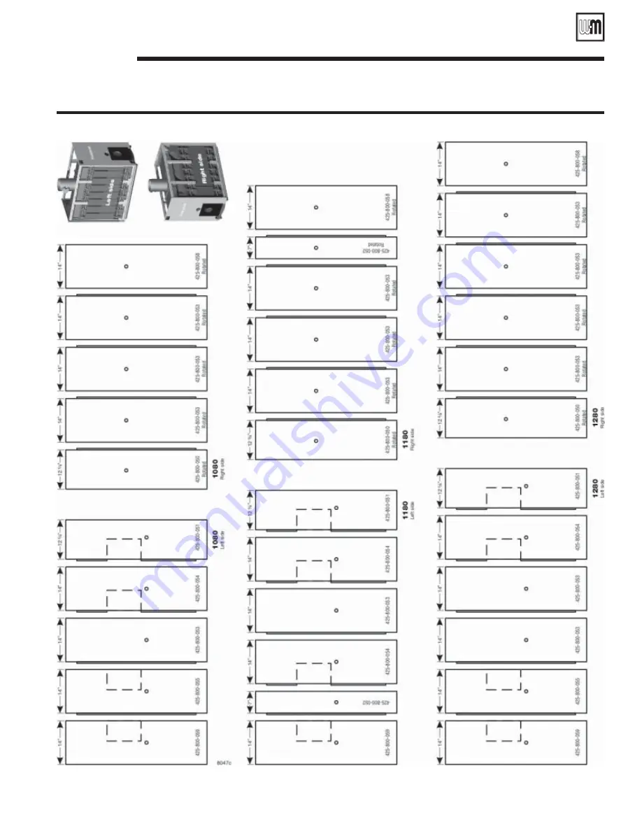
Figure 24    

Jacket side panel placement — Models 1080, 1180, and 1280

Install jacket 

(continued)

9

Summary of Contents for 1080

Page 1: ...er piping and installation when determining boiler location Any claims for damage or shortage in shipment must be filed immediately against the transportation company by the consignee This manual is for use only by your qualified heating installer service technician Boiler and burner must be installed by a qualified service technician We recommend regular service by a qualified service technician ...

Page 2: ... important but not related to personal injury Contents Read all instructions before installing Failure to follow all instructions in proper order can cause severe personal injury death or substantial property damage Do not use petroleum based cleaning or sealing components in boiler system Severe damage to system components can result causing substantial property damage 1 Before installing boiler ...

Page 3: ...inimum clearances to combustible materials 1 Singlewall vent pipe 18 inches 2 Doublewall vent pipe refer to vent pipe manufacturer s recommendations for vent pipe clearances 3 Boiler top 24 inches 4 Boiler front 48 inches 5 Boiler flue 9 inches 6 Boiler rear 9 inches 7 Boiler sides 6 inches Boiler may be installed on combustible flooring See pages 34 and 35 for boiler dimensions Flue pipe breechin...

Page 4: ...s taken from within building each opening should be at least one square inch 1 000 Btuh boiler input and freely connect with areas having adequate infiltration from outside 2 When all air is taken from outdoors each opening should connect directly or by ducts from outdoors or crawl or attic spaces that freely connect with outdoors and sized as listed below a through outside wall or vertical ducts ...

Page 5: ...n front 2 in rear from shipping rails 2 Remove boiler from skid Cables are already attached to block assembly See Table 2 for lifting weight Using crane attach free end of cables to eye of crane Using hoist attach free end of cables to hoist Raise boiler off skid Use pipe rollers under steel skid angles to roll boiler 3 Place boiler in final position Center boiler on foundation if used 4 Level boi...

Page 6: ...ns causing severe personal injury or death 3 Remove any grit from port machined surfaces with clean rag Figure 4 Sealing rope installation Figure 5 Silicone sealant Do not use petroleum based cleaning or sealing compounds in boiler system Severe damage to system components can result causing substantial property damage 4 Place 7 and 3 sealing rings in appropriate port openings SeeFigure4 If sealin...

Page 7: ...ligned lugs If corrections are made and gap still exists contact your Weil McLain distributor or sales office before continuing installation 6 After erecting first intermediate section check both sections for plumb Failure to plumb sections can cause misaligned piping and breeching possibly resulting in property damage 7 Repeat steps 1 5 from Prepare back section page 6 Assemble block continued 3 ...

Page 8: ...ig Water boiler 1 times maximum allowable working pressure MAWP stamped on the boiler nameplate located on boiler jacket front panel Do not exceed above test pressures by more than 10 psig Do not leave boiler unattended Cold water fill could expand and cause excessive pressure resulting in severe personal injury death or substantial property damage 4 Check for maintained gauge pressure and leaks R...

Page 9: ...s bead of sealing rope adhesive in groove on observation port b Position 3 8 sealing rope in groove c Secure assembly to section Use 5 16 18 x slotted head screws 2 Repeat above steps for back observation port assembly Install cleanout plates Cleanout plates must be installed gas tight to prevent possibility of flue gas leakage and carbon monoxide emissions resulting in severe personal injury or d...

Page 10: ...instructions on page 38 of this manual Failure to comply could result in severe personal injury 1 Stand flue collector hood front module item 4 on end as in Figure 8 left side 2 Wipe all flanged surfaces with clean rag 3 Lay flue collector hood gasket item 2 on flange 4 Place flue collector end cap item 1 on gasket Align bolt holes Secure with seven 5 16 x 5 8 flanged bolts and flanged nuts Tighte...

Page 11: ... Installation Start Up Maintenance Parts 11 Part No 550 141 935 0602 Install flue collector continued 6 Figure 10 Flue collector components typical Model 880 collector configurations shown ...

Page 12: ...e causing possible flue gas leakage and carbon monoxide emissions resulting in severe personal injury or death Top flue boilers only 1 See Figure 10 page 11 and Figure 11 page 13 2 Place rear flue cap on rear section a Wipe item 9 Figure 10 rear flue cap gasket surface with a clean rag b Apply a few pieces of double faced tape on the rear flue cap gasket surface c Place the rectangular gasket item...

Page 13: ...lation Start Up Maintenance Parts 13 Part No 550 141 935 0602 Figure 11 Flue collector components by model see Figure 10 page 11 for flue collector components not shown below 6 Install flue collector continued ...

Page 14: ...r flow rate through boiler size piping per Table below Flow at higher rates than shown in Table below for pipe size can damage boiler causing substantial property damage b Locate circulator in supply piping c For return piping use full diameter pipe for 10 times that diameter before making any reduction For example a 4 inch return should not be reduced any closer to boiler return tapping than 40 i...

Page 15: ...er and its secondary pump from aWeil McLain boiler control panel Do not maintain boiler at predetermined water temperature B Primary pump GPM and head calculation should not include secondary boiler circuits Primary pump can operate continuously during heating season C Space 12 maximum or as close as practical D Check valve E Hand valve Expansion tank s relief valves and other accessories are requ...

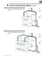
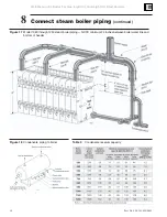
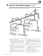
Page 16: ...ing to gravity return systems Consult local Weil McLain distributor or sales office before installing alternate piping 1 Connect supply and return piping a See Table 8 1 Size condensate return piping by pump 2 Size gravity condensate return same as equalizer J pipe size b Install system drain valve in lowest part of return piping close to boiler ASME size requirements are shown in Table 7 page 14 ...

Page 17: ...t steam boiler piping continued 8 Figure 15 Model 380 through 580 steam boiler piping NOTE minimum 24 inches between boiler water line and bottom of header Figure 16 Model 680 through 980 steam boiler piping NOTE minimum 24 inches between boiler water line and bottom of header ...

Page 18: ...s 18 Part No 550 141 935 0602 Table 9 Condensate receiver capacity Figure 18 Condensate piping to boiler Connect steam boiler piping continued 8 Figure 17 Model 1080 through 1280 steam boiler piping NOTE minimum 24 inches between boiler water line and bottom of header ...

Page 19: ... see page 29 Connect traps to condensate receiver Gravity return systems are self levelling if the wet returns are piped to the common system wet return C Install boiler piping as shown in this manual pages 16 through 19 D Install stop valves per ASME code requirements For pump return systems if using automatic steam valves use only slow opening automatic valves Use a Weil McLain Boiler Control Sy...

Page 20: ...utoff gauge glass and gauge glass cocks tri cocks drain cock The boiler contains ceramic fiber and fiberglass materials Use care when handling these materials per instructions on page 38 of this manual Failure to comply could result in severe personal injury Remove jacket parts from cartons 1 Locate jacket cartons 2 Remove jacket parts from cartons as needed Leave in cartons as long as possible to...

Page 21: ... Installation Start Up Maintenance Parts 21 Part No 550 141 935 0602 Figure 20 Installing jacket support brackets and rails and jacket front and rear panels Install jacket continued 9 ...

Page 22: ...square Adjust the jacket support rails forward or backward if needed for square alignment Tighten the screws securing the upper and lower rails to the support brackets Tighten the screws securing the front and back panels to the rails 4 Apply all jacket side panels in the order shown in Figures 22 23 or 24 Remove jacket knockouts as required for tankless heaters Note that panel sequence is not imp...

Page 23: ... Installation Start Up Maintenance Parts 23 Part No 550 141 935 0602 Figure 22 Jacket side panel placement Models 380 480 580 and 680 Install jacket continued 9 ...

Page 24: ...Weil McLain 80 Boiler For Gas Light Oil Gas Light Oil Fired Burners 24 Part No 550 141 935 0602 Figure 23 Jacket side panel placement Models 780 880 and 980 Install jacket continued 9 ...

Page 25: ... Installation Start Up Maintenance Parts 25 Part No 550 141 935 0602 Figure 24 Jacket side panel placement Models 1080 1180 and 1280 Install jacket continued 9 ...

Page 26: ...Weil McLain 80 Boiler For Gas Light Oil Gas Light Oil Fired Burners 26 Part No 550 141 935 0602 Figure 25 Jacket top panel placement Install jacket continued 9 ...

Page 27: ...kless Heater Ratings Figure 26 Tankless Heater Piping Tankless heater model Continuous draw no recovery period GPM Inlet and outlet tappings 78 24 6 5 Pipe tankless heaters 10 Hot water can scald Consumer Product Safety Commission and some states recommend domestic hot water temperature of 130 F or less When installing an automatic mixing valve selection and installation must comply with valve man...

Page 28: ... not pipe to any area where freezing could occur Do not plug valve or place any obstruction in discharge line 3 When installing low water cuttoff a Must be installed if boiler is located above radiation level b May be required on water boilers by certain state local or territorial codes or insurance companies c Install low water cutoff designed for water installationswhereshowninTable 11andFigure ...

Page 29: ... provided with boiler Do not make any other connection in that piping Piperelief valvedischargethroughvertical piping to atmosphere Use rigid material suitable for 375 F threaded one end only Install drain pan elbow to drain condensate Pipe near floor close to floor drain to eliminate potential of severe burns Do not pipe to any area where freezing could occur Do not plug valve or place any obstru...

Page 30: ...Oil Gas Light Oil Fired Burners 30 Part No 550 141 935 0602 Install steam boiler controls continued 12 Figure 29 Steam control siphon and fittings Table 13 Water level control locations Figure 30 Water level control locations see Table 13 ...

Page 31: ...of See Figures 31 and 32 Balanced draft Boiler operates with positive pressure overfire Chimney may provide excess draft which may require a barometric draft control installed and set to provide minimum draft to maintain 0 1 positive pressure at flue collar Minimum chimney height above roof is 3 feet See Figures 33 and 34 Construct metal breeching See Table 14 or Table 15 for minimum breeching dia...

Page 32: ...ive action of fuel oil or liquified petroleum gases Apply sparingly to male threads of pipe joints Do not use any kind of pipe tape 3 Oil piping use flare type fittings not compression type Do not use compression or soldered fittings No safe repair can be made Severe personal injury death or substantial property damage will result Propane boilers see WARNING on page 39 regarding propane gas odoran...

Page 33: ...e petroleum based cleaning or sealing compounds in boiler system Severe damage to system components can result causing substantial property damage Continual make up water will reduce boiler life Minerals can build up in sections reducing heat transfer overheating cast iron and causing section failure For unusually hard water areas or low pH conditions less than 7 0 consult local water treatment co...

Page 34: ...sion forced draft boiler burner units 6 Net I B R ratings are based on net installed radiation of sufficient quantity for the requirements of the building and nothing need be added for normal piping and pickup Water ratings are based on a piping and pickup allowance of 1 15 Steam ratings are based on the following allowances 380 thru 1180 1 333 1280 1 321 An additional allowance should be made for...

Page 35: ... Installation Start Up Maintenance Parts 35 Part No 550 141 935 0602 17 Dimensions and ratings continued ...

Page 36: ...Weil McLain 80 Boiler For Gas Light Oil Gas Light Oil Fired Burners 36 Part No 550 141 935 0602 18 Parts ...

Page 37: ... Installation Start Up Maintenance Parts 37 Part No 550 141 935 0602 18 Parts continued ...

Page 38: ...h potentially contaminated clothes separately from other clothing Rinse clothes washer thoroughly NIOSH stated First Aid Eye Irrigate immediately Breathing Fresh air REMOVAL OF FIBERGLASS WOOL OR INSTALLATION OF FIBERGLASS WOOL COMBUSTION CHAMBER LINING OR BASE PANELS This product contains fiberglass jacket insulation and ceramic fiber materials in combustion chamber lining or base panels in gas f...

Page 39: ...unusual odor If you suspect a leak do not attempt to light the burner Use caution when attempting to light a propane burner or pilot burner This should be done by a qualified service technician particularly if flame outages or pilot outages are common Periodically check the odorant level of your gas Inspect boiler and system at least yearly to make sure all gas piping is leak tight Consult your pr...

Page 40: ...ating contractor whose principal occupation is the sale and installation of plumbing heating and or air conditioning equipment These warranties do not cover 1 Components that are part of the heating systems but were not furnished by Weil McLain as a part of the boiler 2 The workmanship of any installer of Weil McLain s boilers In addition this warranty does not assume any liability of any nature f...

Reviews: