Weil-McLain 94 Series 3 Water and steam boilers —
for Gas, Light Oil, & Gas/Light Oil-Fired Burners
30
Part No. 550-110-275/1018
Install steam boiler controls
(continued)
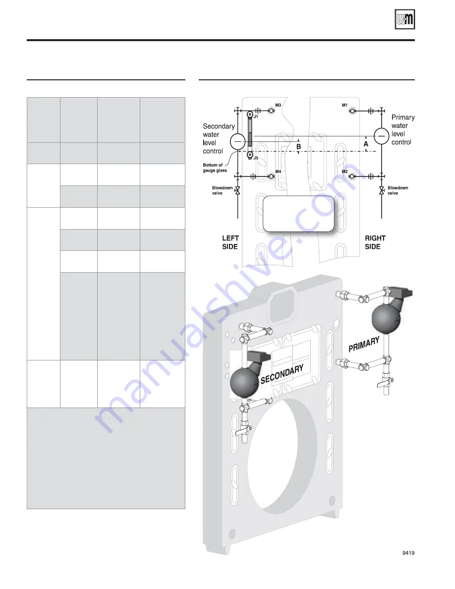
Figure 37
Float-type water level control locations
Primary
water level
control
Casting line
height above
bottom of
gauge glass
Back-up
water level
control
Casting line
height above
bottom of
gauge glass
Note 1
"A"
Notes 1, 2
"B"
61, 63
¼"
None
—
½"
61, 63
¼"
93,
193,
94
(Note 3)
2"
None
—
2"
93, 193, 94
¼"
2"
61, 63
¼"
2"
51-2
(894 to
1594 only)
– or –
51-S-2
(all sizes)
¼"
51-2
51-S-2
(Note 3)
1"to 1¼"
None
—
Notes:
1. Other manufacturers' controls providing similar
functions may be used if properly located and
selected.
2. Use low water cut-off function only. Pump
controller function must only be handled by the
primary control.
3. When pump control is used with feedwater tank,
install pump control on boiler and make-up
water feeder on tank. Use separate low water
cutoff on boiler when back-up is needed. Do not
install combination low water cutoff and feeder
as back-up control on boiler. Feeder will operate
before pump control operates.
Figure 38
Water level control locations (see Figure 37)
Normal water line is
at the center of the
gauge glass.


