background image

Summary of Contents for CGi Series 3

Page 1: ... area or follow the requirements given on page 9 Failure to comply could result in severe personal injury death orsubstantial property damage Thismanualmustonlybeusedbyaqualifiedheatinginstaller servicetechnician BeforeInstalling read all instructions includingthismanual andanyrelatedsupplements Performstepsin theordergiven Failure to comply couldresult in severe personal injury death or substanti...

Page 2: ...stpurgeand waits for the next heatcall Thecontrol module indicatorlightsshownormalsequencewhen the lightsareonsteady Whena problemoccurs thecontrol module flashes combinations of lights to indicate the most likely reason for the problem see page 49 Transfonner The control transformer reduces line voltage to 24 volts for the gas valve and limit circuit Inducer The inducerpulls flue gasesthrough the...

Page 3: ...CGiGAS FIRED wATER eotLER sERIEs 3 Boiler Manual CGi Gas Fired Induced Draft Water Boiler CGi 4 Only 1001 Part Number 550 142 780 0712 3 ...

Page 4: ...d definitions The following defined terms are used throughout tllis manual to bring attention to the presence of hazards of various risk levels or to important information con ming the life ofthe product I WARNINGI lACAUTlONI NOTICE Indicates presence of hazards that will cause severe personal injury death or substantial property damage Indicates presen of hazards that can cause severe personal in...

Page 5: ...fuil to shut off do not tum offor disconnect electrical supply to circulator 1nstead shutoffthegassupplyata location external to the appliance Do not use tllis boiler if any part has been under water Immediatelycall a qualified service teclmician to inspect the boiler and to replace any part of the control system andanygascontrolthathasbeen under water Boller water Do not use petroleum based clean...

Page 6: ...atedon page 15 of this manual Before locating the boiler check the following Check for nearby cOJmection to System water piping Ventingconnections Gas supplypiping Electrical power Checkarea around boiler Remove any combustible materials gasoline and other flammable liquids or other contaminants WARNINGI Failure to keep boilerarea dear and free ofcombustible mate rials gasoline and other flammable...

Page 7: ...ertydamageand reduce boiler life Required MINIMUM clearances Fig 1b I WAR NING I Never Install the boiler In a space with clear anceslessthan theminimum clearancesshown In Figure 1b Failureto complycan resultinsevere personal injury death or substantial propertydam ageand reduced boiler life I Hot water pipes at least h Inch from combustible material 2 Single wall vent pipe atleast 61nches from co...

Page 8: ...etermined that each appliance remaining connected to the common venting system properly vents when tested as outlined above return doors windows exhaust funs fireplace dampers and anyothergas burning appliancetotheirpreviouscon ditions ofuse Anyimproperoperation ofcommonventingsystemshould be correctedsothe installationconfomtswith the National Fuel Gas Code ANSI Z223 1 latest edition Correct by r...

Page 9: ...to body shops Paint orvarnish removers Plastic manufacturing plants Hydrochloric acid muriatic acid Fum ure refinishing areas and establishments Cements and glues New building construction Antlstatlc fabric softeners used In clothes dryers Remodeling areas Chlorine type bleaches detergents and cleaning Garages wHh workshops solvents found In household laundry rooms Adhesives used to fasten buildin...

Page 10: ...ings dlrecUy to the outside sized and located per Figure 3 Figure 4 or Figure 5 2 Buildingsoftypical constructionshould provideadequate combustion air from natural infiltration so additional air openings to the building are not required 3 See Figure 2 Provide two openings through the interior wall within 12 inches ofthe ceilingand the floor sized per Figure 2 TWo openings Air supply directly from ...

Page 11: ...in Figure Ia page 7 To determine if the space is large enough to qualify Add t11e total input ofall appliances in JV BH 1 OOO s of Btuh Multiply this munber tin1es 50 to detem1ine mininmm room volume Exan1ple For a total input of 100 MBH 100 000 Btuh mininmm volume is 50 x 100 5 000 cubic feet At a ceiling height of8 fe et the space must have at least 5 000 8 625 square feet 25 feet x 25 fe et for...

Page 12: ...eath or sub stantial property damage Orifice replacement procedure when required t Remove the screws securing the burner shield and removeburner shield 2 Using a h open end wrench remove the burner orifices from the manifold 3 Apply a small amount ofpipe dope to each of t11e neworifices andinstallint11e manifold us inga I open endwrench JV akesure the ori fices are aligned correctly not cross thre...

Page 13: ...enot included with boiler Fill and pressure test 1 Open the shutoffvalvesyouinstalledon supplyand return connections 2 Slowly open boilerdrain valveand fresh water sup ply to fill boiler with water 3 When water tlo S from shutoff valves close boiler drain valve 4 Closeshutoffvalves Part Number 550 142 780 0712 5 Slowlyreopen boiler drain valve tmtil test pressure on thepressure temperaturegaugerea...

Page 14: ...i 3 4 CGi 4 to CGi 8 5 Il l Chimney I WARNING l Inspect existing chimney before installing boiler Failure to clean or rel lace perforated pipe or lining will cause severe personal inJuryor death Vent sizing given in Table 3 is only a general guideline The vent connector and chimney must be designed sized and constructedin compliancewithallapplicable codes Failureto correctlysiu andinstall thevent ...

Page 15: ...A metal or plastic idC Jltification plate shall be perma nm y mount to thet Xterior of the buildin at a minimum height oftight 8 f t abo t gradtdir tty in line with tht t xhaust fllt terminal for t ht horizontally vmted gasfucltd heating appliance or uipmt nt Tht signshall rt ad in print 5itt no ss than onc half l 2 inch in GAS VENT DIRECTIX BELOW KEEP CLEAR OF AllOBSTRUCTIONs 4 INSPECTION The sta...

Page 16: ... flue gas spillage resulting insevere personal injuryor death 6aodclamp strap Band c lamp sc rew FasNSeal s l r rter Blo t housing outlet 71009 Sand damp screw Bead of se lonl 8 0 ver hous ing outlet 3 Followall applicable national state local or provin cial codes when venting tbe CGi boiler 4 Connect vent starter to blower housing outlet as shown in the Figures 8 through 11 a Do not mix component...

Page 17: ...or or window Condensate can fre e ze causing ice formations 11 Do not connect Anyother appliance to vent pipe Multiple boilers to a common vent pipe Figure 12 Vent termination minimum clearances Optional Snorkeling Part Number 550 142 780 0712 12 Canadian installations See Bl49 1 or Bl49 2 Installation Code Tem1inate vent no less than 6 feet from another combustion air inlet 3 fe et from anyotherb...

Page 18: ...stall horizontal drain tee as dose as possible to boiler in first horizontal run See Figures 13 and 14 9 Do not exceed the maxin1un1 vent system length given in Table 4 page 15 Condensate drain line use only siliconetubingrated for at least 400 F for the first 18 of condensate drain line then other non metallic tubing maybe used Us ing any other material could cause flue gas leakage potentially re...

Page 19: ... l__ Y Note 1 Part Number 550 142 780 0712 J WARNINGJ 1 Elbow and termination coupling wtth screen Elbow and termination coupling with screen Term ination coupling not available Elbow and termination coupling with screen Using any termination other than one ofthose shown couldcausenuisanceoutages andlossofheat resulting in substantial property damage Note 1 DO NOTus horizontal tee with CGJ 1 or CG...

Page 20: ...evere personal injury death or substantial property damage Test the operation ofthe valve after filling and pressurizing system bylifting the lever Makesure thevalve discharges freely If the valve fails to operate correctly replace it with a new reliefvalve Circulator Thecirculator isshipped loose wiringpre attached to boiler to allow you to locate it either in the return or supply piping as desir...

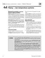
Page 21: ...ipingup towards tank I inch per 5 feet of piping I WARNING UseFigure 16or Ftgure 17 onlyforsingle zonesystemsdesigned for return wateratleast I30 F For systems with low return water temperature possible such as converted gravity systems and radiant heatingsystems refer to the special piping suggestions ofpages 24 29 Failure to preventlowreturn watertemperature to theooilercouldcausecorrosionoftheo...

Page 22: ...olttransfom1erto powerthe zonevalves Size the transformer to handle the total rated load ofall connected zone valves Radiant heating systems Preferably use primary secondary piping as shown in Figures 20 or 21 on page 25 Alternatively use the method of either Figure 22 or Figure 23 on page 27 Do not use the piping of Figure 24 system bypass because this method does not control radiant system suppl...

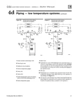
Page 23: ...or zone circulator 11 Fill valve 5 Zone valve 6 Drain valve 9 Reliefvalve I WARNINGl 12 Diaphragm type or bladder type expansion tank if used For dosed type expansion tank pipe from top ofair separator to tank fitting as Ill Figure 17 13 Air separator and automatic vent if used Note that the fill valve mustalwaysbeconnectedtotheexpansion tank regardlessofloca tionofexpansion tankcircu1ator orairse...

Page 24: ...Figures 20 and 21 only I Setthevalveswhile thesystemiscool settingfor the coldest expected water temperature usually 600F since thesystem will often drop to room tempera ture between cycles 2 Startwith valve 7a fully dosed and 7b fully open 3 Gradually openvalve7a while dosingvalve7buntil the temperatureatgauge 8 reads I30 Fwhen gauge 4a reads 60 F 4 Note thatvalve 7a regulates the amount ofhotwa ...

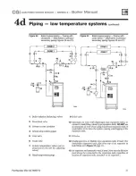
Page 25: ...temperature gauge 71023 71022 9 Reliefvalve 10 Automatic air vent with diaphragm type expansion tank or connect to tank fitting closed type expansion tank DO NOT useanautomaticair ventwhen using d osed typeexpansion tank It would allow air to leave the system causing waterlogging of the expansion tank 11 Fill valve 12 Diaphragm type or bladder type expansion tank if used For dosed type expansion t...

Page 26: ...ed on all systems to assure reliable adjustment of the bypass valves The boiler mounted temperature pressure gauge can be used if a separate temperature gauge is not installed Valve adjustment t Start with valve 7a fully dosed and 7b fully open 2 Gradually open valve 7a while dosing valve 7b until the temperature atgauge 8 reads60 F higher than gauge 48 A minimum 60 F temperature rise through the ...

Page 27: ...valves 8 Blend temperature gauge r f zoN e 2 J ZONE1 f 1 1 i 5 T 1 it 1 6 Cold M I I 71024 71025 9 Reliefvalve 10 Automatic air vent with diaphragm type expansion tank or connectto tankfitting closed type expansion tank DO NOTuse an automaticair ventwhen usingclosed type expansion tank It would allow air to leave thesystem causing waterlogging ofthe expansion tank 11 Fill valve 12 Diaphragm type o...

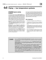
Page 28: ...t from radiators near the end ofthesystem Valve adjustment I Startwith valve 7a fully dosed and 7b fully open 2 Graduallyopen valve 7a while dosingvalve7buntil the temperatureatgauge 8 readsatleast 130 Fatall times 3 Valve 7a regulatestheamountofboilersupplywater mixed withreturnwater Valve 7b causesa pressure drop in the system needed to balance flow through valve 7a and the system 4 The valve ad...

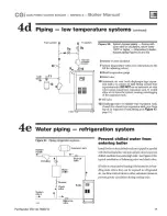
Page 29: ...nk 11 Fill valve 12 Diaphragm type or bladder type expansion tank ifused For d osed typeexpansion tank pipe from top ofair separator to tank fitting as in Rgure 17 page 21 4e Water piping refrigeration system Figure 25 Piping refrigeration systems System I I Expansion tank supply I T t Shut off Circulator valve Water chiller t Strainer Cheek Boiler B l valve II System t return Balancing 1 1 valve ...

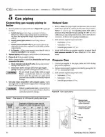
Page 30: ...threadsofpipejoints sothatpipedope does not block gas flow I WARNING Failure to apply pipe dope asdetailedabove can result in severe personal injury death or Natural Gas I Refer to Table 7 for pipe length and diameter Base on rated boiler input divide by 1 000 to obtain cubic feet per hour Table 7 is only for gas with specific gravity 0 60 with a pressure drop through the gas piping of 0 30 w c Fo...

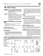
Page 31: ...ilergives settingfor control moduleandgasvalve Alsosee instructions with them1ostat DHW 1 O nnect DHWaquastatas showninwiring below Economy ftmction isn t utilized with DHW input Junction Box furnished 1 O nnect 120 V AC power wiring as shown in Figure 27 2 Fused disconnect or service switch 15 amp recommended may be mounted on this box For those installations with local codes which prohibit insta...

Page 32: ...roleum based cleaning or sealing compounds in boiler system Severe damage to boiler will occur resulting in substantial property damage Eliminate all system leaks Continual fresh makeup water will reduce boiler life Minerals can build up in sections reducing heat transfer overheating c ast iron and causing section failure Verify water chemistry Consult local water treatment companies for unusually...

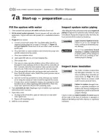
Page 33: ...nstalled in system open manual airvents in systemone at a time beginning with lowest floor Close vent when watersquirtsout Repeatwith remaining vents 4 Openautomatic air vent diaphragm type orbladder typeexpansion tanksystems only one tum 5 Open other vents a Starting on the lowest floor open air vents one at a time until water squirts out b Repeat with remaining vents 6 Refill to correct pressure...

Page 34: ... thatadditional heatwillbeneeded The knoblabeledECONOMY ADJUST providesan adjustment between maximize JV AX and minimize MIN the delay The max immn JV AX adjustment position shouldbeused toma imizeenergysavings Turningthe knobcounterclockwisedecreasesthe delaytime andshouldonly beusedin theeventthatthe heatedspacebecomesuncomfortable ADJUST ECONOMY TO DESIRED POSmON MAX IS THE PREFERRED SETTING IM...

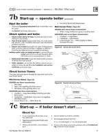
Page 35: ...tion port in the base burner shield Pilot burner flame Figure 28 PROPER pilot flame characteristics t Blue tlante 2 Inner cone engulfing pilot flame sensor 3 Pilot flame sensor glowing cherry red IMPROPER pilot flame charactf f istics I Overtired Large flame lifting or blowing past pilot tlante sensor 2 Undertired Small flame hmer cone not engttlfing pilot flame sensor 3 Lack ofprimaryair Yellow f...

Page 36: ...reignite 0 Test ignition system safetydevice a Connect manometer to outletside ofgas valve b Start boiler allowing for normal start up cycle to oc cur and main burners to ignite c With main burners on manually shut offgassupply at manual main shutoff gas valve Burners should go off d Open manual main shutoffgllS valve Manometer should confirm there is no gas flow e Pilot will relight flame sensing...

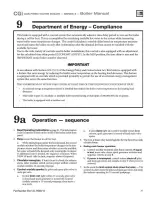
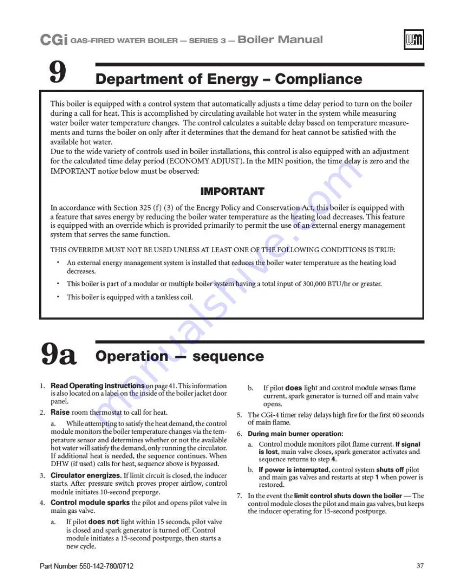
Page 37: ...otal input of 300 000 BTU hr or greater Thisboiler is equipped with a tankless coil 9a Operation sequence I Read Operating instructionsonpage41 Thisinfom1ation isalso locatedon alabelon the insideoftheboilerjacketdoor panel b Ifpilot does light and control module senses flame current sparkgenerator is turnedoffand main valve opens 2 Raise room them10stat to call for heat a Whileattemptingtosatisfy...

Page 38: ...circuit uml oo rol5Ci06e l YES jl jl jl 0 0 Rollot t TfECOf llac f 6CfOSe l Inducer Inducertum on YES li ji li 0 0 5 Pressure circuit Pre ft 6 1 1 1 CCifltaoi5CI06e l YES ll I I II li 0 35sec Prepurge 1t 1r 10 eOOnCI5 G Pilot flame proven Gaova Yeopen 6 6 6 6 6 15sec YES PilOtremoifn on BCi IHptOOI I h heat 7 Limit cycle uml ct CIJlopen YES 6 6 6 0 0 Ga5va YeCI06e0 8 Aameoutage Flameout NO 6 6 6 0...

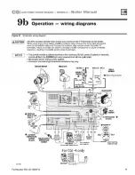
Page 39: ...lure to comply can resullln damage to boiler components orcause unreliable operation resuhlng In possible severe property damage NOTICE The control module Is polarity sensitive to the Incoming 120VAC power If polarity is reversed control wil flash the POWER lightwhen powered and wil not cycte boiler All contacts shown without power applied Connector and status light locations orientations may vary...

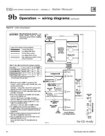
Page 40: ...ied with the appli ance must be replaced use minimum 105 cwireor equivalent Exception wires to arollout TFE must be200 cor equivalent 4 Thermostat anticipatorsetting singlezone see T ableGfor anticipator setting depending onwhichgas valve isinstaledinboiler 5 For muhiplezoning useeither zonevalves or circulators Refer to thecomponent manufacturer sII structionsand this manual for application and w...

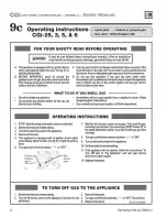
Page 41: ...y electric switch do not use any phoneInyourbuilding Immediately call your gas supplier from aneighbo s phone Follow thegassupplier sinstructions Ifyoucannotneachyourgassupplier callthefiredepartment OPERATING INSTRUCTIONS 1 STOPI Readthesafetyinformationaboveonthislabel 2 Setthethermostattolowestsettlng 3 Turnoffall electrical powertotheappliance 4 Removefrontpanel 5 This appliance is equipped wi...

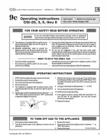
Page 42: ...tric switch do not use any phoneinyourbuilding Immediately call your gas supplier from aneighbor s phone Follow thegassuppliefsinstructions Ifyoucannotreachyourgassupplier callthefiredepartment OPERATING INSTRUCTIONS 1 STOPI Readthesafetyinformationaboveonthislabel 2 Setthethermostattolowestsetting 3 Tumoffallelectricalpowertotheappliance 4 Removefrontpanel 5 This appliance is equipped withan igni...

Page 43: ...tely call your gas supplierfrom aneighbor s phone Follow thegassupplier sInstructions Ifyoucannotreachyourgassupplier callthefiredepartment OPERATING INSTRUCTIONS 1 ST OP ReadthesafetyInformation aboveonthislabel 2 Setthethermostattolowestsetting 3 Tum offallelectricalpowertotheappliance 4 Removefrontpanel 5 T his appliance is equipped with an ignition device which automatically lightsthe pilot Do...

Page 44: ...lding Immediately call your gas supplier from a neighbor s phone Follow thegassupplier s instructions Ifyoucannotreachyourgassupplier callthefiredepartmenl OPERATING INSTRUCTIONS 1 STOP Read the safety information above on this label 2 Set the thermostat to lowestsetting 3 Tum off all electrical power to the appliance 4 Remove jacket front paneL 5 This appliance is equipped with an ignition device...

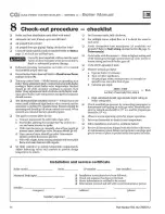
Page 45: ...Expansion tank Boiler relief valve Review Review with owner Owner maintenance see CGi User s Information Manual for instructions Check boiler area Check air openings Check boiler pressure temperature gauge Check boiler interior piping Check venting system Check air vents Check boiler relief valVe Check condensate drain system Check automatic air vents H used Test low water cutoff H used Oil induce...

Page 46: ...ed isolate the boiler and provide outside combustion air See national provincial or local codes for further infom1ation Air openlng s I Verifythatcombustion and ventilation airopeningsto the boilerroom and or building are open and unobstructed 46 2 Verify that boiler vent discharge is clean and free of obstructions Flue gas vent system I Visually inspect entire flue gas venting system for blockage...

Page 47: ...mpletely dear run a vacuum at the burner inlet while cleaning the burner ports with a wire brush Thevacuum will helpto draw anyairborne material out ofthe burner Part Number 550 142 780 0712 4 Reinstall components starting with the burner tray then the pilot bracket assembly burner baffle and air inlet top and front panels 5 Follow the start up procedure in the boiler manual Condensate drain syste...

Page 48: ...usually in the attic or closet Has a gauge glass and overflow pipe to a drain Closed type weldedgas tightandlocated above boiler Tank is partially tilled with water leaving an aircushion for expansion Make sure tllis type oftank is fitted with a tank IHtlng such as the B G Tank Trot or Taco Taco TroL This fitting reduces gravity circula tion of air saturated tank water back to the system and preve...

Page 49: ...l DOl seal properly lace the relief yaJ Ensure 1ha1 the n for t 1 liefvah e etpmg is lhe valve and DOl over prmurization of 1he syslem due 10 expansion lank walerlogging or undersizing Figure 35 Relief valve typical Part Number 550 142 780 0712 0 Review with owner I Review lhe User s Information Manual with lhe owner 2 Emphasize the need 10 perform 1he mainlenance schedule specified in the User s ...

Page 50: ...igh tire IO O w c b Microammeter with a minimum scale rangeof0 25 CGi 4 only Manifold pressure low tire 3SO w c whilein low fire at start up 60seconds c Continuitychecker d U tube manometer c Ifnecessary adjustgas pressureonthegasvalveasshownbelow After adjustments refertopage35tocheck the flame 2 Check for 120 VAC minimum 102 VAC to maximmn 132 V AC to boiler 3 Make sure them1ostat is calling for...

Page 51: ...CGi 5 CGi 6 and CGi 8 CGi 7 Figure 36 Manometer connections Whitb Whi R ed i l 1p I Side lmcnorPOOCI 1 11 1 Part Number 550 142 780 0712 lnchesW C 1 79 1 36 1 12 0 80 0 75 Ave collector Temperature sensor I The boiler temperaturesensor is a resistance typedevice 2 TheTable 10 below shows the correctvalue for the sensorat various temperatures 3 Use the resistance values at 32 F 60 F 70 F and 2 t2 F...

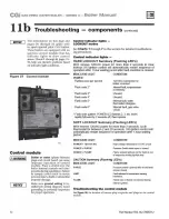
Page 52: ...ontrol will automatically restart sequence of operation after 1hour waiting period after fault condition is cleared INDICATOR LIGHT CONDITlON POWER Aashes once per second Aash code 2 Aash code 3 Aash code4 Aash code 5 Aash codes 120 VAG connection to boiler reversed Internal fatlt iaoprocessor or memory Unused Unused Internal fault water thermistors disagree Internal fault gas valve circuit Aash c...

Page 53: ... ircufU s 00 n B i H H 11 0 t POWER g 0 TSTAT CIRC 0 0 0 0 0 c LIMIT PURGE FLAME l I s I 2 i s r 6 120VACto lndUOI rmator 120 VAC to tT nSfor r Sense w ire to flame sensor 120VAC IN Transformur 24 VAC to control c irouit11 Part Number 550 142 780 0712 120 VA to induc er motor 1201 ACH 120VACN cv 120 VAC to clrcwl 0 Fl m ne wrr to pilot Tllermlstor Common Thcrmi11tor 2 BoUw Suppfy Tem attlre sensor...

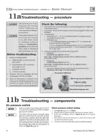
Page 54: ...rt Chart Reconnect 120 VAC IN plug light flashing 4 6 Remove transformer plug Figure 38 Item 2 page 53 For insufficient heat or no heat problem go to on control module Chart 7 if POWER light is on steady wtth no other 1 Using voHmeter check across left side top and bottom light flashing pins of transformer receptacle Does voltmeter indicate 120 VAC No Yes Usually indicates polarity on incoming 120...

Page 55: ...nal thermostat across the wires circuit wires to the boiler thermostat wires and allow the There should NEVER be a voltage reading boiler to cycle Did you find a voffage across the 1 Vo externalthermostatcircuit wires Yes No Leave external boiler thermostat connection wires If no vonage is found under any condition of the external disconnected from boiler thermostat circuit connect the two boiler ...

Page 56: ...53 Wait 5 minutes from plug receptacle of control module Is PURGE light nashing Place voltmeter leads across the 120 VAC N and 120 VAC H pins ofthe INDUCER receptacle middle and No bottom pins I I Yes Does the voltmeter indicate 120 VAC No Yes Try reseating plug in module receptacle and Boiler should be in restart If inducer still does not normal operating wort replace inducer sequence Are vent or...

Page 57: ...al Section 9c Look through the pilot inspection port to see if the pilot is burning during the prepurge period first 30 seconds of Do FLAME and POWER lights stillflash operation No I Yes Is pilot burning during prepurge period No II Yes Replace control module Retest Replace gas valve Allow boiler to continue cycling Retest boiler Are FLAME POWER lights flashing Are FLAME and POWER lights flashing ...

Page 58: ...lug receptacle of control module Place vokmeter leads across the 120 VAC N and Wa 5 minutes 120 VAC H pins ofthe INDUCER receptacle middle and is PURGE light Hashing bottom pins Does the voltmeter indicate 120 VAC No I Yes No I Yes Replace inducer assembly Boiler should be in Retest normal operating sequence Observe operation until Remove one of the wires connected to tile pressure thermostat is s...

Page 59: ...e range breaker Contact gas supplier to correct Remove bumer shield see pressure or gas supply No Yes Figure 40 itMJ 4 page 63 for location t TURN OFF POWER t to boier at seiVice switch or t TURN OFF POWER to boilerat service switch or breaker Verify pilot gasline is not breaker Check flame signal Detach sense lead from ignition control kilked obstructed or Remove burner shield see Figure 38 item ...

Page 60: ...ce of operation Figure 30 page 39 60 If you have less than sufficient heat Is vent oioina free ofblockaae No I I Yes Correct conditions and Is manifold pressure recheck operation See Figure 30 page 38 for normal sequence of operation Check heat loss calculation versus boiler size Clock gas input 3 50 w c on natural gas 10 0 w c on propane Yes II No I r Replace timer relay CGi 4 Only Replace temper...

Page 61: ...tion and part number of replacement part Results from using modified or other manufactured parts will not be covered bywarranty and maydamageboiler or impair operation I NOTICE Weii Mclain part numbers are found in We ll Mcl a in Boilers and I Controls Repair Parts Lists I WARNJNGI The boilercontains ceramic fiber and fiberglass materials Usecarewhen handling these materials per instructions on Pa...

Page 62: ...ansition CGi 3 381 354 595 shown section CGi 4 321 114 331 assembly CGi 4 381 354 596 assembly CGi 5 321 114 332 CGi 5 381 354 597 CGi 6 321 114 333 CGi 6 381 354 598 CGi 7 321 114 334 CGi 7 381 354 599 CGi S 321 114 335 CGi S 381 354 600 not Section replacement kit includes 381 354 527 shown sealsand sealant for 1 joint 9 T emperature Tasseron 381 356 5n Sensor TSL0550 4 Tie rod 1 CGi 25 and CGi ...

Page 63: ...CGi GAS FIRED wATER BOILER sERIEs 3 Boiler Manual 12C Replacement parts base Figure 40 Base assembly Part Number 550 142 780 0712 I I j 63 ...

Page 64: ... 003 796 8b Rear spacing strip CGi 25 CGi 3 550 320 160 CGi 4 550 320 161 CGi 5 550 320 162 CGi 6 550 320 163 CGi 7 550 320 164 CGi 8 550 320 165 Be Nut hex 5mm Zp 550 320 170 9 Base insulation kit CGI 25 CGi 3 381 354 330 CGI 4 381 354 331 CGi 5 381 354 332 CGi 6 381 354 333 CGI 7 381 354 334 CGI 8 381 354 335 10 Boiler leg kit 550 320 219 11 Manifold CGi 25 CGi 3 591 126 735 CGi 4 591 126 736 CG...

Page 65: ... 223 311 381 355 420 381 355 558 CGi 5 CGi 6 381 355 877 381 355 907 431 223 311 381 355 427 381 355 565 CGi 6 CGi 7 381 355 883 381 355 910 431 223 311 381 355 434 381 355 572 CGi 7 CGi 8 381 355 889 381 355 913 431 223 311 381 355 441 381 355 579 CGi 8 6 7 8 9 10 Panel door Cross tie Panel interi Panel rear Not shown bottom front with insulation with insulation gold touch up paint Boiler Model B...

Page 66: ... 000 000 short shank FitUngs shown 81 8 shipped loos6 with boiler 3 Drain valve Conbtaco 31 606 01 511 210 423 FIIOngs shown 81 8 Included with boiler Hammond 710 511 246 392 Valve Matco Norca 205F04 511 246 392 Watts BD 2C 511 246 392 4 Circulator Taco 007 511 405 113 FitUngs shown 81 8 shippedloose with boiler 5 Circulator gasket unl ersaJ 2 perboiler Wei Mclaln 590 317 535 not Circulatorhardwar...

Page 67: ...t shown Wiring harness Thermostat not shown Wiring harness Sensor CGI 4 Only Manufactur er Honeywell White Rodgers Honeywell Honeywell White Rodgers Weii Mclei n Honeywell White Rodgers Honeywell Honeywell White Rodgers Weii Mclei n United TechnoJogies Weit Mclei n Tri Detta Cleveland Tri Detta Tri Detta Tri Detta ABB lydall Weii Mclein Weii Mclein Weii Mclein Manufacturer s part number VR8204A200...

Page 68: ...1 y Gas supply piping Drain valve J Gas supply entrance right or left side Pressure temperature gauge Hotel 8041 c r s upplyand return tappings are both 1 4 NPT SeeTable6 page 20for recommended system wp plyandretump plng sizes Nole2 Sollercirculator is shippOO loose Circulatormay be mounted on eilher boiler supply or return piping C irculator11angeprovided witfl boilerissame size as recommend ed ...

Page 69: ...ment of Energy 3 Net AHRI ratings are based on net Installed radiation of sufficient quantity for the requirements of the building and nothing need be added for normal piping and pickup Ratings are based on a pip ing and pickup allowance of 1 15 An additional allowance should be made for unusual piping and pickup loads 4 CGi boilers require special venting consistent with Category I or Ill boiler ...

Page 70: ... plastic bag for disposal 0 Wash potentially contaminated clothesseparately from otherclothing Rinseclotheswasher thoroughly N OSH stated First Ald 0 Eye Irrigate immediately 0 Breathing Fresh air 70 REMOVAL OF FIBERGLASS WOOL or INSTALLATION OF FIBERGLASS WOOL COMBUSTION CHAMBER LINING OR BASE PANELS I WARNING Thisproductcontains fiberglass jacket insulation and a ranticfiber materi als in combus...

Page 71: ...CGi GAS FIRED wATER BOILER sERIEs a Boiler Manual Notes Part Number 550 142 780 0712 71 ...

Page 72: ...CGi GAS RREo wATER BOILER SERIEs a Boiler Manual WEIL m LAIN 72 Wei Mcl ail 500 BlaineStreet Michigan City IN 4636 2388 lmp ww M t il mclain com Part Number 550 142 780 0712 ...

Reviews: