background image

Part number 550-110-260/0107

5

GOLD CGs Gas-Fired Water Boiler — Boiler Manual

11d

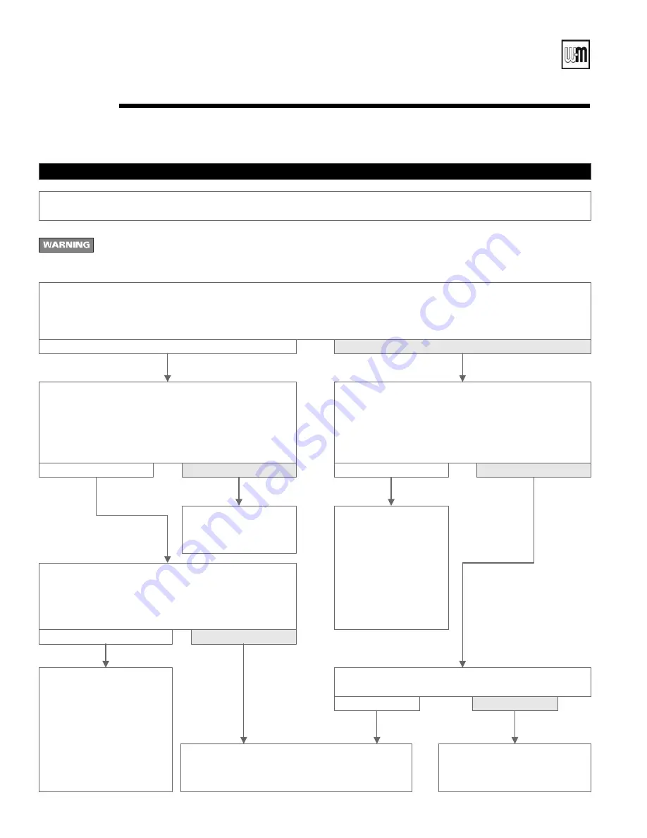
Troubleshooting — control module lights 

(cont.)

CHART 6

PRESS SWITCH 

light flashing and 

POWER 

light on steady

Electrical shock hazard — Wherever you see �

TURN OFF POWER

�, follow the instructions. Failure to follow 

instructions could result in severe personal injury, death or substantial property damage.

—  Usually indicates pressure switch opened during run cycle  —

—  May also be caused by wind gusts in excess of 31 mph for non-direct vent sidewall-vented boilers  —

• Boiler should be in 

normal operating 

sequence.

• Observe operation until 

thermostat is satisfied 

and inducer has 

completed its post-

purge cycle.

• Remove one of the wires connected to the pressure 

switch.

• Check continuity across the switch terminals.

Does the ohmmeter indicate the switch is closed?

• Inspect and check wire 

harness from control 

module to pressure switch.

• Reseat connector in control 

module receptacle.

• If harness is intact and 

properly seated, but 

problem persists, replace 

control module.

• Retest.

• Check air pressure switch per manual Section 11.

• Replace if necessary. Retest.

• Replace inducer 

assembly.

• Retest.

No

Yes

• Remove 

INDUCER 

plug (

Figure 25, Item 6

, page 46

)

from plug receptacle of control module.

• Place voltmeter leads across the 

120 VAC N

 and 

120 VAC H

 pins of the 

INDUCER 

receptacle (left column 

center and right column bottom pins).

Does the voltmeter indicate 

120 VAC

?

No

Yes

Are vent or combustion air passages blocked?

No

Yes

• Clear passages and recycle 

boiler.

• Recheck boiler operation.

• Wait 5 minutes.

                       Is 

PRES SWITCH

 light flashing?

• Reset boiler control by turning off power at service switch or turning down thermostat for at least 45 seconds.

• Thermostat should call for heat and appropriate zone valves open.

Does blower motor operate?

No

Yes

No

Yes

Summary of Contents for GOLD CGS 550-110-260/0107

Page 1: ...s in the order given Failure to comply could result in severe personal injury death or substantial property damage Installation Startup Boiler Manual Maintenance Parts GOLD CGs Gas Fired Water Boilers DO NOT USE BOILER DURING CONSTRUCTION unless you provide dust free air to the boiler area or follow the requirements given on page 9 Failure to comply could result in severe personal injury death or ...

Page 2: ...cate the most likely reason for the problem see page 45 Transformer The control transformer reduces line voltage to 24 volts for the gas valve and limit circuit Inducer The inducer pulls flue gases through the boiler causing air to be pulled in through the air intake opening The inducer pushes the flue gases through the vent pipe as well Air pressure switch The air pressure switch signals the cont...

Page 3: ...Part number 550 110 260 0107 GOLD CGs Gas Fired Water Boiler Boiler Manual GOLD CGs Gas Fired Induced Draft Water Boiler ...

Page 4: ...jury death or substantial property damage Indicates presence of hazards that will or can cause minor personal injury or property dam age Indicates special instructions on installation operation or maintenance that are important but not related to personal injury or property damage How it works 2 3 Hazard definitions 4 Please read before proceeding 5 1 Prepare boiler location 6 11 2 Prepare boiler ...

Page 5: ...ter Do not add cold water to hot boiler Thermal shock can cause sections to crack Glycol potential fire hazard All glycol is flammable when exposed to high temperatures If glycol is allowed to accumulate in or around the boiler or any other potential ignition source a fire can develop In order to prevent potential severe personal injury death or substantial property damage from fire and or structu...

Page 6: ... Gas supply piping Electrical power Check area around boiler Remove any combustible materials gasoline and other flammable liquids or other contaminants Check for nearby connection to System water piping Venting connections Gas supply piping Electrical power Check area around boiler Remove any combustible materials gasoline and other flammable liquids or other contaminants Failure to keep boiler a...

Page 7: ...ide proper air flow around the boiler The free area of each opening after deducting for louvers must be at least one square inch per 1 000 Btuh of boiler input If the building is of unusually tight construction see page 10 for definition the air openings must connect directly to outside or the building must have air openings to the outside as specified on page 10 If clearances are equal to or grea...

Page 8: ... as determined using the appropriate tables in Part 11 of that code Canadian installations must comply with B149 1 or B149 2 Installation Code CGs special vent system Vent system The CGs boiler requires a special vent system designed for pressurized venting Model CGs 3 is rated ANSI Z21 13Category IV pressurizedvent likelytocondense in the vent Models CGs 4 5 and 6 are rated Z21 13 Category III pr...

Page 9: ...the boiler air intake at all times you must inspect the boiler at least once weekly When inspecting clean the burners if necessary using the procedure given on page 39 Failure to follow these guidelines could result in severe personal injury death or substantial property damage Products to avoid Areas likely to have contaminants Spray cans containing chloro fluorocarbons Dry cleaning laundry areas...

Page 10: ...o the appropriate vent supplement and the instructions in this manual Two options are available sidewall or vertical direct vent Each requires a special vent component kit Sizing air openings Air openings provide for ventilation as well as combustion air to prevent overheating of the boiler controls and boiler space Air is also needed for other appliances located in the same space Use Figure 3 pag...

Page 11: ...Part number 550 110 260 0107 11 GOLD CGs Gas Fired Water Boiler Boiler Manual Figure 3 Sizing air openings for CGs installations ...

Page 12: ... or substantial property dam age 3 Reinstall inlet air box top panel Orifice replacement procedure when required 1 Remove the screws securing the inlet air box top panel 2 Remove inlet air box top panel and inspect the fiber gasket Verify the gasket is in good condition and can seal around the complete perimeter of the air box Replace the gasket if necessary 3 Using a 7 16 open end wrench remove t...

Page 13: ...ir during the fill Valve and nipple are not included with boiler Fill and pressure test 1 Open the shutoff valves you installed on supply and return connections 2 Slowly open boiler drain valve and fresh water sup ply to fill boiler with water 3 When water flows from shutoff valves close boiler drain valve 4 Close shutoff valves 5 Slowly reopen boiler drain valve until test pressure on the pressur...

Page 14: ...ystems large volume systems originally designed for circulation by natural convection rather than a pump Chillers or air handling units Install boiler such that Chilled medium if used is piped in parallel with heating boiler Use appropriate valves to prevent chilled medium from entering boiler Consult I B R Installation and Piping Guides If boiler is connected to heating coils located in air handl...

Page 15: ...ure 5 1 Ensure expansion tank size will handle boiler and system water volume and temperature See tank manufacturer s instructions for details 2 Connect tank to NPT tapping located behind supply outlet using NPT piping Pitch any horizontal piping up towards tank 1 inch per 5 feet of piping Undersized expansion tanks cause system water to be lost from relief valve and makeup water to be added throu...

Page 16: ...so use the piping shown in Figure 12 on page 23 system bypass if the reduced flow rate in the heating system will not cause heat distribution problems Failure to prevent low return water temperature to the boiler could cause corrosion of the boiler sec tions or burners resulting in severe personal injury death or substantial property damage Radiant heating systems Preferably use primary secondary ...

Page 17: ...k 11 Fill valve 12 Diaphragm type or bladder type expansion tank if used For closed type expansion tank pipe from top of air separator to tank fitting as in Figure 5 page 15 13 Air separator and automatic vent if used Note that the fill valve must always be connected to the expansion tank regardless of location of expansion tank circulator or air separator 3c Water piping multiple zones continued ...

Page 18: ...ange in the heating circuit rate and temperature distribution Figures 8 and 9 page 19 show suggested bypass ar rangements using primary secondary bypass piping preferred for low temperature systems such as radiant heating systems or converted gravity systems For alternatives see pages 20 through 23 The bypass valves in Figures 8 and 9 items 7a and 7b provide mixing of hot boiler outlet water with ...

Page 19: ...use an automatic air vent when using closed type expansion tank It would allow air to leave the system causing waterlog ging of the expansion tank 11 Fill valve 12 Diaphragm type or bladder type expansion tank if used For closed type expansion tank pipe from top of air separator to tank fitting as in Figure 5 page 15 13 Air separator and automatic vent if used Note that the fill valve must always ...

Page 20: ...to the instructions following Figures 10 and 11 are alternative piping suggestions for converted gravity large water content or steam systems or radiant heating system for use when primary secondary piping can t be applied Figure 12 page 23 is another alternative using system bypass in place of boiler bypass piping Figure 12 however is not suitable for radiant heating applications because it does ...

Page 21: ...ansion tank It would allow air to leave the system causing wa terlogging of the expansion tank 11 Fill valve 12 Diaphragm type or bladder type expansion tank if used For closed type expansion tank pipe from top of air separator to tank fitting as in Figure 5 page 15 13 Air separator and automatic vent if used Note that the fill valve must always be connected to the expansiontank regardlessof locat...

Page 22: ...eturn water to the boiler Valve 7b will most often be full open but may need to be slightly closed on some low pressure drop systems in order to cause enough flow through valve 7a Figure 12 is an alternative piping method that provides return water temperature control for boilers installed on converted gravity systems large water content or steam systems Do not apply the piping of Figure 12 on rad...

Page 23: ... of air separator to tank fitting as in Figure 5 page 15 Figure 12 System bypass piping Zoning with zone valve or circulators return water 130 F or higher Alternative to boiler bypass piping Figures 10 and 11 page 21 Figure 13 Piping refrigeration systems Water piping refrigeration systems Prevent chilled water from entering Install boiler so that chilled medium is piped in parallel with the heati...

Page 24: ...be assured to be free of contaminants Refer to page 9 for a list of potential contaminants and locations likely to contain them Operating the boiler with contaminated air will damage the boiler sections and vent resulting in possible boiler failure or leakage of flue products causing severe personal injury death or substantial property damage Install vent piping and air piping if used per appropri...

Page 25: ...as to boiler a Install drip leg at inlet of gas connection to boiler Where local utility requires drip leg to be extended to the floor use appropri ate length of pipe between cap and tee b Install ground joint union for servicing when required c Install manual shutoff valve in gas supply piping outside boiler jacket when required by local codes or utility requirements d In Canada When using manual...

Page 26: ... x 4 cover plate on the boiler junction box and mount the service switch remotely as required by the code For your safety turn off electrical power supply at service entrance panel before making any electrical connections to avoid possible electric shock hazard Failure to do so can cause severe personal injury or death Wiring must be N E C Class 1 If original wiring as supplied with boiler must be...

Page 27: ...fe Minerals can build up in sections reduc ing heat transfer overheating cast iron and causing section failure Verify water chemistry Consult local water treatment companies for unusually hard water areas above 7 grains hardness or low pH water conditions below 7 0 Boiler water pH of 7 0 to 8 5 is recommended Freeze protection when used Use antifreeze made especially for hydronic systems Inhibited...

Page 28: ...boiler life Minerals can build up in sections reducing heat transfer overheating cast iron and causing section failure 1 Check system piping for leaks If found shut down boiler and repair immediately 2 Vent air from system usingmanual vents Airinthesystemwillinterfere with circulation and cause heat distribution problems and noise 3 Inspect vent system thoroughly for signs of deterioration from co...

Page 29: ...e 17 PROPER main burner flame characteristics 1 Yellow orange streaks may appear caused by dust IMPROPER main burner flame characteristics 1 Overfired Large flames 2 Underfired Small flames 3 Lack of primary air Yellow tipping on flames sooting will occur Start up if boiler doesn t start 7c 1 Loose connections blown fuse or service switch off 2 High limit switch set below boiler water tempera ture...

Page 30: ...e pilot flame and main burners will reignite Set limit control s to system temperature requirements Adjust balancing valves and controls to provide design temperature to system For multiple zones adjust flow so it is about the same in each zone Verify thermostat heat anticipator if available set properly Refer to Field wiring manual Section 6 Thermostat s Cycle boiler with thermostat Raise to high...

Page 31: ...trol module senses flame current spark generator is turned off and main valve opens 5 During main burner operation a Control module monitors pilot flame current If signal is lost main valve closes spark gen erator activates and sequence returns to step 4 b If power is interrupted control system shuts off pilot and main gas valves and restarts at step 1 when power is restored 6 In the event the lim...

Page 32: ...Part number 550 110 260 0107 32 GOLD CGs Gas Fired Water Boiler Boiler Manual Operation wiring diagrams 9b Figure 19 Schematic wiring diagram ...

Page 33: ...Part number 550 110 260 0107 33 GOLD CGs Gas Fired Water Boiler Boiler Manual Figure 20 Ladder wiring diagram ...

Page 34: ...Part number 550 110 260 0107 34 GOLD CGs Gas Fired Water Boiler Boiler Manual 9c Operating instructions CGs 3 to CGs 6 Spark pilot Natural or propane gas Gas valve Honeywell VR8204 VR8304 ...

Page 35: ...Part number 550 110 260 0107 35 GOLD CGs Gas Fired Water Boiler Boiler Manual Operating instructions CGs 3 to CGs 6 Spark pilot Natural or propane gas Gas valve White Rodgers 36E 9c ...

Page 36: ...Part number 550 110 260 0107 36 GOLD CGs Gas Fired Water Boiler Boiler Manual 9c Operating instructions CGs 3 to CGi 6 Spark pilot Natural or propane gas Gas valve White Rodgers 36C ...

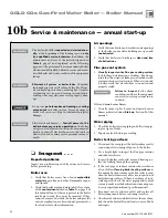
Page 37: ...ntenance procedures given throughout this manual and in com ponent literature shipped with the boiler Failure to perform the service and maintenance could result in damage to the boiler or system Failure to follow the directions in this manual and component literature could result in severe personal injury death or substantial property damage VERIFY PROPER OPERATION AFTER SERVICING ...

Page 38: ...ained per this manual 5 Reconnect vent to inducer outlet and replace all boiler components before returning to service 6 Check inside and around boiler for evidence of any leaks from the boiler If found locate source of leaks and repair The boiler should be inspected and started annu ally at the beginning of the heating season only by a qualified service technician In addition the maintenance and ...

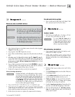
Page 39: ...uilding freeze damage Read and follow the WARNING on page 9 Failure to inspect and clear gas burner ports could result in severe personal injury death or substantial property damage 1 Inspect each burner to insure that every port is completely open 2 If any port is not completely clear run a vacuum at the burner inlet while cleaning the burner ports with a wire brush The vacuum will help to draw a...

Page 40: ...ated above highest radiator or baseboard unit usually in the attic or closet Has a gauge glass and overflow pipe to a drain Closed type welded gas tight and located above boiler Tank is partially filled with water leaving an air cushion for expansion Make sure this type of tank is fitted with a tank fitting such as the B G Tank Trol or Taco Taco Trol This fitting reduces gravity circula tion of ai...

Page 41: ...terways are clear Certain naturally occurring mineral deposits may adhere to the valve rendering it in operative When manually operating the lever water will discharge and precautions must be taken to avoid contact with hot water and to avoid water damage Before operating lever check to see that a discharge line is connected to this valve directing the flow of hot water from the valve to a proper ...

Page 42: ...ll be exposed to freezing temperatures If using antifreeze in system do not drain 2 Follow shutdown procedure 3 Remove venting system connection to boiler 4 Remove top jacket panel Turn back insulation 5 Remove collector box transition assembly Clean sealant from assembly and sections 6 Remove radiation plates hanging between sec tions 7 Remove burners from base Brush and vacuum burners to remove ...

Page 43: ...y checker d U tube manometer 2 Check for 120 VAC minimum 102 VAC to maximum 132 VAC to boiler 3 Make sure thermostat is calling for heat and contacts including appropriate zone controls are closed Check for 24 VAC between thermostat wire nuts and ground Check the following 1 Wire connectors to control module are securely plugged in at module and originating control 2 Air pressure switch hoses are ...

Page 44: ...re 24 Manometer connections Table 6 Pressure switch setpoint for elevations above 2 000 ft contact your local Weil McLain sales office for details Troubleshooting air pressure reading 1 If manometer reading is lower than the setpoint of the switch see Table 6 check for possible causes blockage in hoses obstruction in inducer housing outlet loose inducer wheel on motor shaft inducer motor not in pr...

Page 45: ...ally indicates reversed polarity of 120 VAC power wires POWER and TSTAT CIRC lights flashing Usually indicates stray voltage on external thermostat circuit wires usually due to miswired 3 wire zone valve POWER and PRESS SWITCH lights flashing Usually indicates pressure switch is closed when it should not be or pressure switch failed to close within 5 minutes of inducer starting POWER and FLAME lig...

Page 46: ...Part number 550 110 260 0107 46 GOLD CGs Gas Fired Water Boiler Boiler Manual Troubleshooting control module continued 11c Figure 25 Control module connections ...

Page 47: ...Y plug Figure 25 item 2 page 46 on control module Using voltmeter check across top and bottom pins of PRIMARY receptacle Does voltmeter indicate 120 VAC No Yes Reinstall 120 VAC transformer PRIMARY plug Using voltmeter check across pins of receptacle Does voltmeter indicate 24 VAC No Yes Chart 2 Chart 6 TSTAT CIRC light flashing Chart 3 Chart 4 PRESS SWITCH light flashing Chart 5 FLAME light flash...

Page 48: ...ermostat leads two black low voltage leads in J box Connect a voltmeter across these two incoming wires Close each thermostat zone valve and relay in the external circuit one at a time and check the voltmeter reading across the wires There should NEVER be a voltage reading If a voltage does occur under any condition check and correct the external wiring This is a common problem when using 3 wire z...

Page 49: ...n 11b Replace if necessary Retest Try reseating plug in module receptacle and restart If inducer still does not work replace inducer assembly Retest No Yes Wait 45 seconds Does inducer motor operate No Yes Remove INDUCER plug Figure 25 Item 6 page 46 from plug receptacle of control module Place voltmeter leads across the 120 VAC N and 120 VAC H pins of the INDUCER receptacle left column center and...

Page 50: ...45 seconds Turn on power to boiler Restart boiler following Operating instructions in this manual Section 9c Do FLAME and POWER lights still flash Boiler should now operate normally Original flashing FLAME light caused by gas valve not operating properly See normal sequence of operation Figure 18 page 31 Replace gas valve Retest boiler Are FLAME and POWER lights flashing No Yes No Yes Are manual m...

Page 51: ...er at service switch or breaker Check flame signal Detach sense lead from igntion control Figure 25 item 8 page 46 Connect negative lead of MICROAMMETER to control sense terminal Figure 25 item 8 page 46 Connect positive lead of MICROAMMETER to sense wire DISCONNECT red wire connected to terminal B see Table G page 33 of the gas valve Turn on power to boiler and allow to cycle As soon as pilot is ...

Page 52: ...er indicate the switch is closed Inspect and check wire harness from control module to pressure switch Reseat connector in control module receptacle If harness is intact and properly seated but problem persists replace control module Retest Check air pressure switch per manual Section 11 Replace if necessary Retest Replace inducer assembly Retest No Yes Remove INDUCER plug Figure 25 Item 6 page 46...

Page 53: ...should be in normal operating sequence See normal sequence of operation Figure 18 page 31 If you have less than sufficient heat Is vent or combustion air piping free of blockage No Yes Correct conditions and recheck operation See Figure 18 page 31 for normal sequence of operation Contact your Weil McLain sales representative Replace control module Retest Repair replace circulator Retest Repair rep...

Page 54: ... and include description and part number of replacement part Results from using modified or other manufactured parts will not be covered by warranty and may damage boiler or impair operation Weil McLain part numbers are found in Weil McLain Boilers and Controls Repair Parts Lists The boiler contains ceramic fiber and fiberglass materials Use care when handling these materials per instructions on p...

Page 55: ...Part number 550 110 260 0107 55 GOLD CGs Gas Fired Water Boiler Boiler Manual Replacement parts section assembly 12b Figure 26 Section assembly ...

Page 56: ...Part number 550 110 260 0107 56 GOLD CGs Gas Fired Water Boiler Boiler Manual Replacement parts base 12c Figure 27 Base assembly ...

Page 57: ...ase right side panel in Base assembly 7 Base back panel in Base assembly 8 Base front cross tie assembly in Base assembly 9 Pilot bracket 450 003 689 10 Pilot burner assembly Natural gas Pilot burner assembly Propane gas 511 330 080 511 330 081 11 Inlet air box front panel in Inlet air box front panel kit 12 Inlet air box front panel gasket Use Gasket kit 13 Inlet air box top panel in Inlet air bo...

Page 58: ...Part number 550 110 260 0107 58 GOLD CGs Gas Fired Water Boiler Boiler Manual Replacement parts jacket 12d Figure 28 Jacket assembly ...

Page 59: ...699 431 223 311 431 223 311 381 355 403 381 355 413 381 355 420 381 355 427 381 355 706 381 355 713 381 355 720 381 355 727 381 355 707 381 355 714 381 355 721 381 355 728 CGs 3 CGs 4 CGs 5 CGs 6 Boiler Model 7 8 9 10 11 12 Not shown Boiler Model Cross tie bottom front Panel interior with insulation Panel rear with insulation Air inlet fitting Inlet air hose Hose clamp 3 Gold touch up paint Weil M...

Page 60: ...ameter short shank Fittings shown are shipped loose with boiler Weil McLain 380 000 000 3 Drain valve Fittings shown are included with boiler Conbraco Hammond Valve Matco Norca Watts 31 606 01 710 205F04 BD 2C 511 210 423 511 246 392 511 246 392 511 246 392 4 Circulator Fittings shown are shipped loose with boiler Bell Gossett Grundfos Taco NRF 22 103253 UP15 42FR TB4 007 511 405 118 511 405 126 5...

Page 61: ... 3 through CGs 6 Honeywell VR8204M2701 511 044 354 2 Pilot assembly kit with orifice and aluminum pilot gas tubing Weil McLain 511 330 081 Natural gas and propane gas components 3 Control module United Technologies 1107 1 511 330 090 not shown Wiring harness Weil McLain 591 319 795 4 Air pressure switch 1 79 I W C CGs 3 1 48 I W C CGs 4 1 22 I W C CGs 5 0 95 I W C CGs 6 Tri Delta PPS10171 3013 PPS...

Page 62: ...Part number 550 110 260 0107 62 GOLD CGs Gas Fired Water Boiler Boiler Manual Dimensions 13a Figure 31 Dimensional drawing ...

Page 63: ...00 60 300 51 600 50 000 1 5 85 3 3 CGs 4 85 000 100 000 85 000 90 000 76 500 74 000 2 1 84 6 3 CGs 5 112 000 133 000 112 400 119 000 100 600 97 000 2 7 84 0 3 CGs 6 140 000 167 000 140 300 150 300 126 300 122 000 3 3 83 4 3 Notes 1 Add PIN for natural gas boiler PIL for propane gas boiler 2 Based on standard test procedures prescribed by the United States Department of Energy 3 Net I B R ratings a...

Page 64: ...n from the boiler and place it in a plastic bag for disposal Wash potentially contaminated clothes separately from other clothing Rinse clothes washer thoroughly NIOSH stated First Aid Eye Irrigate immediately Breathing Fresh air REMOVAL OF FIBERGLASS WOOL or INSTALLATION OF FIBERGLASS WOOL COMBUSTION CHAMBER LINING OR BASE PANELS This product contains fiberglass jacket insulation and ceramic fibe...

Reviews: