background image

30

Repair information and repair instructions

7.11 Replacing the fan

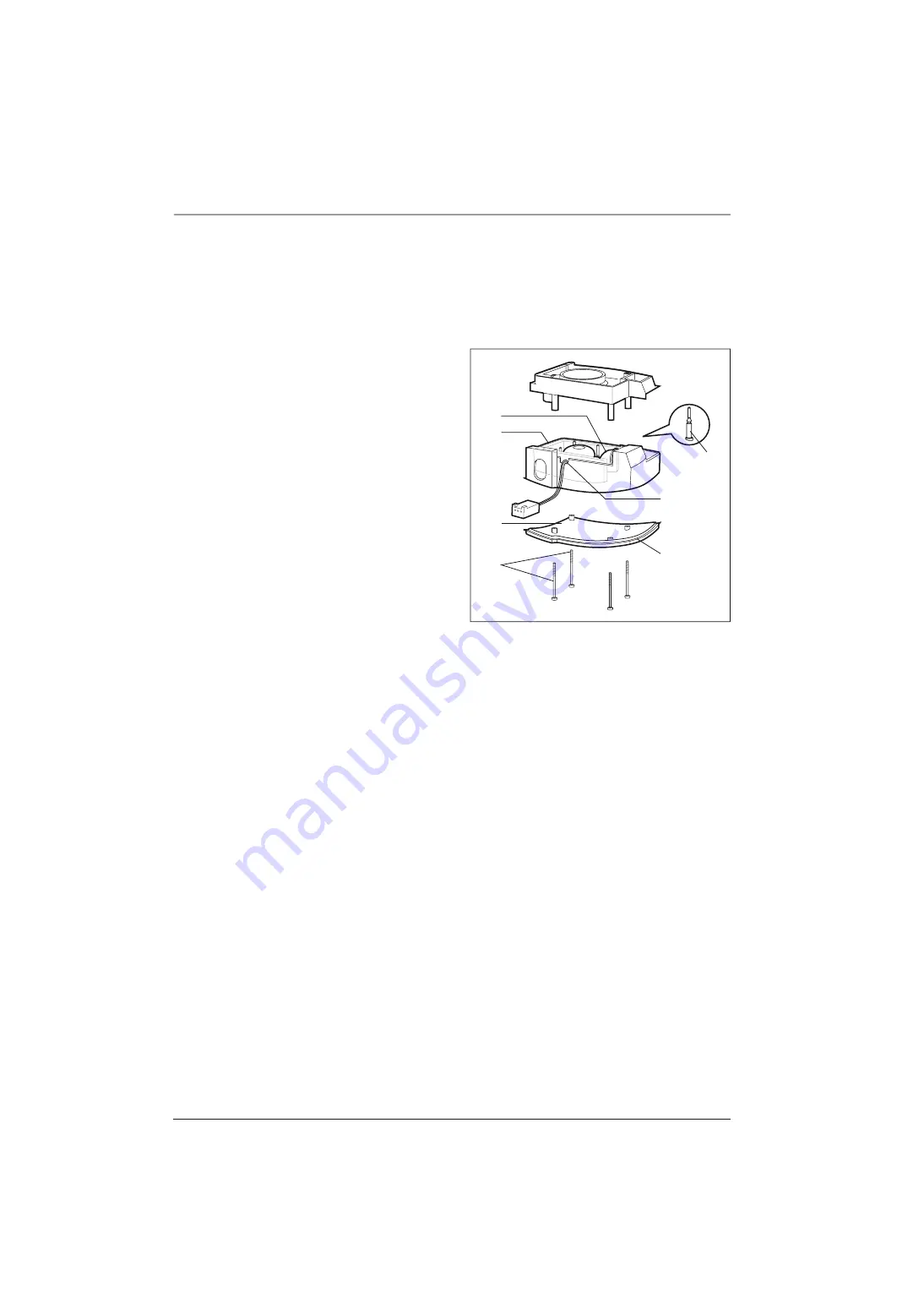
Remove the fan

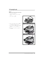
1. Open the unit (see “7.4 Opening the unit” on 

page 23).

2. Remove the box 

53

 (see “7.10 Replacing the 

baffle box” on page 28 steps 

1.

 to 

2.

).

3. Remove the four 

69

 screws.

4. Remove the box cover and the attached 

60


foam part.

5. Pull the two parts of the box apart.

6. Pull the decoupling tube 

55

 out of the motor 

frame’s bore hole.

7. Loosen the motor mount 

54

. Cut the mount 

using scissors or scalpel.

8. Remove the fan 

65

.

Inserting the fan

1. Place three new motor mounts 

54

 into the box.

2. Insert the fan 

65

 into the motor frame and 

attach it using the motor mounts 

54

. Pull the 

motor mounts through the bore holes of the fan 
to reach the surrounding notch.

3. Apply a small amount of 70 % Isopropanol 

solution on the decoupling tube’s 

55


circumference and attach it to the box. 


The tube’s notch must completely lock into the 
bore hole rim.

4. Reconnect the two parts of the box. 

Pay 

attention to proper alignment of the foam part 61 
and the correct cable lead. The cable must be 
placed in the appropriate cut-out. 

5. Place the cover on the box and insert the 

screws.

6. Insert the box (chapter 7.10, page 28 steps 

1.


to 

4.

).

7. Insert the main circuit board (chapter 7.6, 

page 25, steps 

1.

 to 

4.

).

8. Close the unit (chapter 7.5, page 24).

9. Check that everything is working properly 

(chapter 5., page 15).

69

60

Cover

55
61

Cut-out

54

Summary of Contents for homecare SOMNObalance

Page 1: ...M 24405 SOMNOcomfort 2 e with SOMNOaqua WM 24455 autoCPAP Units SOMNObalance SOMNObalance white WM 27400 SOMNObalance white with SOMNOaqua WM 27440 SOMNObalance anthracite WM 27410 SOMNObalance anthra...

Page 2: ...ns 21 7 1 General 21 7 2 Tools and facilities 21 7 3 Sequence of repairs 22 7 4 Opening the unit 23 7 5 Closing the unit 24 7 6 Replacing the main circuit board 25 7 7 Replacing the front panel foil 2...

Page 3: ...ents In the event of a warranty claim send the devices to WEINMANN In order to handle warranty or goodwill requests we will require you to submit proof of purchase invoice of the customer Repair and s...

Page 4: ...ance e 2 Power supply cable 9 Breathing tube 10 Exhalation system 7 Unit outlet 6 Serial interface 12 Head gear 5 Cover 11 Mask 8 Adapter 14 Service symbol 15 Softstart time 16 Automatic switch on off...

Page 5: ...ressure 12 Head gear accessory Helps locate the mask correctly and securely 13 Humidifier activated This symbol appears when the humidifier is in operation The current humidity level is displayed 14 S...

Page 6: ...SOMNOcomfort 2e connection for setting the therapy parameters with SOMNOadjust WM 23930 and SOMNOsupport WM 23975 by specialist staff or to control the O2 connection valve WM 24042 Max current consum...

Page 7: ...ng Symbol Meaning SOMNOcomfort 2 SOMNOcomfort 2e SOMNObalance SOMNObalance e SN Unit serial number Unit of protection class II Permitted temperature for storage 40 C to 70 C 0 95 Permitted humidity fo...

Page 8: ...nd SOMNOcomfort 2e are not designed for life support 2 2 Intended use SOMNObalance and SOMNObalance e SOMNObalance and SOMNObalance e are autoCPAP devices for treating sleep related respiratory disord...

Page 9: ...witch off automatically The therapy parameters are set by trained personnel using the remote control system SOMNOadjust or the evaluation program SOMNOsupport The therapy unit will automatically save...

Page 10: ...ompartment cover Clean areas of extreme soiling Opening the unit see chapter 7 4 page 23 Closing the unit see chapter 7 5 page 24 Following components to be wiped down with disinfectant Unit housing F...

Page 11: ...unit 6 Attach the humidifier where applicable Please refer to chapter 3 4 Humidifier of the instructions for use Clear the filter change indicator When switching the unit on press and hold the on off...

Page 12: ...ase both buttons 4 SOMNOcomfort 2 SOMNOcomfort 2e By pressing the on off switch briefly 19 the servicing indicator can be set and deleted SOMNObalance SOMNObalance e Briefly pressing on off switch 19...

Page 13: ...k according to the instructions for use Open the unit according to 7 4 Replace 68 67 coarse and fine dust filters Vacuum clean inner housing and filter compartment clean areas of extreme soiling Close...

Page 14: ...eaned in order to transfer it to a new patient the following steps should be taken For hygiene reasons we recommend that the plastic parts are replaced after a maximum of two years use The replacement...

Page 15: ...page 42 Operating hours Humidity level Softstart time and initial pressure Mode for CPAP therapy pressure for APAP bottom and top pressure limit rise speed as per patient record If you detect errors...

Page 16: ...and tight If this is not the case replace the foil see chapter 7 7 on page 26 2 You should now establish the power supply by connecting the power supply 3 and the power supply cable 2 to the unit and...

Page 17: ...device If softstart is active switch it off using button 20 8 Compare the value displayed by the pressure measurement device with the value in the LC display After approx 1 minute the maximum allowabl...

Page 18: ...ction of the humidifier 1 Check the plastic housing visually if tears damage or heavy soiling are found the plastic parts or gaskets must be replaced 2 Fill the humidifier up to the mark with water 3...

Page 19: ...he CPAP is 1 hPa after 1 minute Main circuit board defective Replace main circuit board Chapter 7 6 Page 25 Unit will not switch on by breathing into the mask while in automatic mode Automatic mode sw...

Page 20: ...Page 25 Err E EEPROM data erased damaged Err S Hardware defective fuse motor driver Err c EEPROM cell containing calibration data erased defective Err A Pressure sensor defective Err P Hardware defec...

Page 21: ...ds and your workspace are clean when performing repairs After every repair a servicing check must be performed see 5 Final test on page 15 When replacing components or single parts use genuine Weinman...

Page 22: ...etermine the order of required repair steps Opening the unit Replace fuse Replace housing lower part Remove main circuit board Replace front panel foil Remove the display Remove baffle box Remove fan...

Page 23: ...side down on a non slip surface 3 Remove the six screws 70 4 Remove the lower part of the housing 48 with a swivelling motion away to the side 5 Remove the connector X1 from the circuit board and pull...

Page 24: ...e main circuit board 44 inside the unit 4 Attach the connecting cable 64 to its mount 5 Place the lower part of the housing 48 on the upper part at 47 Please make sure the main circuit board is aligne...

Page 25: ...from the pressure sensor or pull out the tube adapter of the pressure measurement tube 4 der Winkelt lle auf dem Drucksensor 5 Remove the main circuit board 44 Inserting the main circuit board 1 Atta...

Page 26: ...3 2 Remove the main circuit board chapter 7 6 page 25 steps 1 to 5 3 Loosen the front panel foil 52 using a knife and remove it 4 Degrease this section of the housing using a 70 Isopropanol solution 5...

Page 27: ...Using other fuses may cause damage to the main circuit board 3 Close the unit chapter 7 5 page 24 4 Check that everything is working properly chapter 5 page 15 7 9 Replacing the display 1 Open the un...

Page 28: ...sert Tighten the screw 71 firmly but not too tight Note If the screws are too tight it may become difficult to install the cover 5 5 Insert the main circuit board chapter 7 6 page 25 steps 1 to 4 6 Cl...

Page 29: ...Pull the protective backing off the adhesive tape and stick on foam 59 Use the crosses as a positioning aid 4 Apply a small amount of 70 Isopropanol solution on the decoupling tube s 50 circumference...

Page 30: ...otor frame and attach it using the motor mounts 54 Pull the motor mounts through the bore holes of the fan to reach the surrounding notch 3 Apply a small amount of 70 Isopropanol solution on the decou...

Page 31: ...9 page 27 steps 1 to 5 4 Disassemble the adapter pressure gland 78 5 Remove the box 53 chapter 7 10 page 28 steps 1 to 2 You have now removed all of the parts Now begin to reassemble them back into th...

Page 32: ...tion and repair instructions 13 Insert a new fine dust filter 67 followed by a coarse dust filter 68 14 Reattach the filter compartment cover 22 15 Check that everything is working properly chapter 5...

Page 33: ...WM 15668 30 Servicing set white WM 15687 31 Servicing set dark grey WM 15688 32 Instructions for use SOMNOcomfort 2 SOMNOaqua DE WM 16892 33 Instructions for use SOMNObalance SOMNOaqua DE WM 66200 34...

Page 34: ...ront foil SOMNObalance e WM 24438 WM 24484 WM 27408 WM 27428 53 Baffle box installed WM 24439 54 Motor mount WM 24444 55 Decoupling tube inside WM 24446 56 Pressure gland WM 24447 57 Cleaning plug pac...

Page 35: ...e 1 Cover cap 1 Adapter installed 1 Label recycling Set WM 15688 for SOMNOcomfort 2 SOMNObalance dark grey Consisting of 1 Coarse dust filter 1 Fine filter 1 affle box installed 1 Gasket fan housing 1...

Page 36: ...ring device accuracy 0 1 e g type GMH 3110 with pressure sensor 0 25 hPa Type GMSD 25 MR Can be ordered from Greisinger electronic GmbH Hans Sachs Str 26 D 93128 Regenstauf Germany Tel 49 9402 8500 Fa...

Page 37: ...ock level of protection from electric shock protection against damaging ingress of water operating mode Protection class II Type B IPX1 Constant operation Electromagnetic compatibility EMC as per EN 6...

Page 38: ...life 250 hours with normal room air SOMNOcomfort 2 SOMNOcomfort 2e SOMNOcomfort 2 with SOMNOaqua SOMNOcomfort 2e with SOMNOaqua SOMNOaqua Product class as per 93 42 EEC II a Dimensions WxHxD in mm 140...

Page 39: ...tric shock level of protection from electric shock protection against damaging ingress of water operating mode Protection class II Type B IPX1 Constant operation Electromagnetic compatibility EMC as p...

Page 40: ...10 hPa 5 hPa Long term constant pressure level prEN 17510 1 2005 p 0 7 hPa p 0 6 hPa p 0 5 hPa p 0 4 hPa p 0 1 hPa p 0 7 hPa p 0 6 hPa p 0 5 hPa p 0 4 hPa p 0 1 hPa Finefilter separation level to 1 m...

Page 41: ...Nominal output of HF equipment in W Safety distance dependent on transmission frequency in m 150 kHz 80 MHz 80 MHz 800 MHz 800 MHz 2 5 GHz 0 01 0 1 0 04 0 07 0 1 0 37 0 11 0 22 1 1 2 0 35 0 70 10 3 7...

Page 42: ...yes no Control panel and display Chapter 5 2 5 Page 16 yes no Functionality Measured pressure comparison Target_______________ hPa Actual_______________ hPa Chapter 5 2 6 Page 17 yes no Functionality...

Page 43: ...comfort 2e SOMNObalance SOMNObalance e WM 16988 Date __________________________ Signature __________________________ Measure taken see also done Cleaning and disinfecting during repairs Chapter 4 2 Pa...

Page 44: ...weg 40 D 22525 Hamburg T 49 0 40 5 47 02 0 F 49 0 40 5 47 02 461 E info weinmann de www weinmann de Center for Production Logistics Service Weinmann Ger te f r Medizin GmbH Co KG Siebenst cken 14 D 24...

Reviews: