background image

WM 66

611 07/

202

1

OXYWAY

EN

243

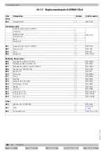
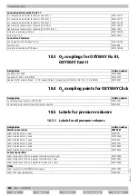
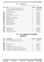
Replacement parts

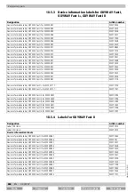
18.5.2

Labels for OXYWAY Fix I, OXYWAY Fix III

Designation

Article number

Device information label, OXYWAY Fix I, for WM 30101

WM 75107

Device information label, OXYWAY Fix I, for WM 30102

WM 75108

Device information label, OXYWAY Fix I, for WM 30103

WM 75109

Device information label, OXYWAY Fix I, for WM 30104

WM 75110

Device information label, OXYWAY Fix I, for WM 30106

WM 75111

Device information label, OXYWAY Fix I, for WM 30107

WM 75112

Device information label, OXYWAY Fix I, for WM 30115

WM 75253

Device information label, OXYWAY Fix I, for WM 30123

WM 75113

Device information label, OXYWAY Fix III, for WM 30301

WM 76973

Device information label, OXYWAY Fix III, for WM 30302

WM 76983

Device information label, OXYWAY Fix III, for WM 30303

WM 76994

Device information label, OXYWAY Fix III, for WM 30304

WM 76986

Device information label, OXYWAY Fix III, for WM 30305

WM 76979

Device information label, OXYWAY Fix III, for WM 30306

WM 76999

Device information label, OXYWAY Fix III, for WM 30307

WM 76991

Device information label, OXYWAY Fix III, for WM 30308

WM 76982

Device information label, OXYWAY Fix III, for WM 30311

WM 76975

Device information label, OXYWAY Fix III, for WM 30321

WM 76977

Device information label, OXYWAY Fix III, for WM 30322

WM 76985

Device information label, OXYWAY Fix III, for WM 30323

WM 76996

Device information label, OXYWAY Fix III, for WM 30324

WM 76989

Device information label, OXYWAY Fix III, for WM 30325

WM 76981

Device information label, OXYWAY Fix III, for WM 30326

WM 77011

Device information label, OXYWAY Fix III, for WM 30331

WM 77452

Device information label, OXYWAY Fix III, for WM 30335

WM 77453

Device information label, OXYWAY Fix III, for WM 30341

WM 76976

Device information label, OXYWAY Fix III, for WM 30342

WM 76984

Device information label, OXYWAY Fix III for WM 30343

WM 76995

Device information label, OXYWAY Fix III for WM 30344

WM 76988

Device information label, OXYWAY Fix III for WM 30346

WM 77070

Device information label, OXYWAY Fix III for WM 30347

WM 76992

Device information label, OXYWAY Fix III for WM 30351

WM 76974

Device information label, OXYWAY Fix III for WM 30361

WM 76978

Device information label, OXYWAY Fix III for WM 30363

WM 76997

Device information label, OXYWAY Fix III for WM 30364

WM 76997

Device information label, OXYWAY Fix III for WM 30375

WM 76980

Device information label, OXYWAY Fix III for WM 30381

WM 77171

Device information label, OXYWAY Fix III for WM 30391

WM 77172

Device information label, OXYWAY Fix III for WM 30401

WM 77449

Device information label, OXYWAY Fix III for WM 30413

WM 75152

Device information label, OXYWAY Fix III for WM 30417

WM 77019

Device information label, OXYWAY Fix III for WM 30421

WM 77012

Device information label, OXYWAY Fix III for WM 30423

WM 75375

Device information label, OXYWAY Fix III for WM 30416

WM 75153

Back

Forward

Contents

Previous page

Next page

Summary of Contents for OXYWAY Click

Page 1: ...OXYWAY Pressure reducer from serial number 1810000 Fix I Fix III fixed Fast I Fast I Fast II Fast III multistep Fine I variable Click multistep Service Manual...

Page 2: ...g the contents indicator 25 7 7 Checking the static outlet pressure p4 26 7 8 Checking the constant output flow 28 7 9 Checking the accessories 29 8 Final inspection OXYWAY Fast I OXYWAY Fast I OXYWAY...

Page 3: ...for leaks 56 11 5 Checking the constant output flow at the inhalation outlet 57 11 6 Checking the accessories 58 12 Faults 59 13 Repairs to OXYWAY Fix I OXYWAY Fix III 62 13 1 General instructions 62...

Page 4: ...20Disassembling assembling the orifice plate assembly 106 14 21Replacing the threaded pin in the multistep flow selector 108 14 22Replacing the multistep flow selector 109 14 23Replacing the balls 109...

Page 5: ...5 30Disassembling assembling the cover assembly 159 15 31Replacing the O ring in the housing cover 164 15 32Replacing the O rings in the multistep flow selector 165 15 33Replacing the housing cover 16...

Page 6: ...selector assembly 212 17 10Disassembling assembling the orifice plate assembly 215 17 11Replacing the threaded pin in the multistep flow selector 216 17 12Replacing the multistep flow selector 217 17...

Page 7: ...50 20 1 Accessories and other parts 250 21 Required auxiliary equipment 251 21 1 Tools 251 21 2 Test equipment and auxiliary equipment 253 22 Technical data 255 23 Technical changes 256 23 1 Technical...

Page 8: ...ion the local accident prevention regulations and general safety provisions for use of the device apply Diagrams in this service manual serve to improve basic understanding and may differ from the act...

Page 9: ...gh the connecting bolt with hand screwed connection and 2 filters in series When the cylinder valve is open the cylinder pressure in the pressure reducer is reduced by a piston with spring to 0 5 bar...

Page 10: ...sure OXYWAY Fast I Fast I Fast III Mechanics Housing Housing cover Inhalation outlet Orifice plate Multistep flow selector Multistep flow selector Connecting bolt with hand screwed connection Disposab...

Page 11: ...nder pressure can be read off at the contents indicator The pressure reducer is protected against excessive pressure by a safety valve OXYWAY Fast II has a pressure outlet as well as the inhalation ou...

Page 12: ...ng operation the oxygen enters the housing from the central gas supply system via the O2 sampling point on the pressure reducer with a pressure of 4 5 bar With OXYWAY Click there is an orifice plate w...

Page 13: ...OXYWAY Fast II OXYWAY Fast III OXYWAY Click Used for inhalation flow dosing Piston exception OXYWAY Click Reduces the inlet pressure to a constant pressure together with the spring Spring exception OX...

Page 14: ...service manual Never perform any work on the pressure reducer other than that which is described here Never make construction changes to the pressure reducer Only use original accessories and spare pa...

Page 15: ...he device and all the screwed unions completely free from oil and grease Do not immerse the device in a disinfectant or any other cleaning solution Wash your hands before working on the oxygen supply...

Page 16: ...ntents of this chapter can be found in the instructions for use for this medical device at www weinmann emergency com Please observe the information given in the instructions for use especially the sa...

Page 17: ...ith the applicable European directives xxl min Maximum output at pressure outlet The pressure reducer must not come into contact with flammable substances oil alcohol grease etc as there is a risk of...

Page 18: ...manufacturer Also observe and comply with the maintenance intervals for devices in storage Follow the maintenance intervals as stated on the device labeling Perform a full function check before every...

Page 19: ...OXYWAY Fix I OXYWAY Fix III page 22 OXYWAY Fast I OXYWAY Fast I OXYWAY Fast III see 8 Final inspection OXYWAY Fast I OXYWAY Fast I OXYWAY Fast III page 30 OXYWAY Fast II see 9 Final inspection OXYWAY...

Page 20: ...ated parts The device accessories and other parts may be contaminated and infect the technicians with bacteria or viruses Sent in parts which are visibly contaminated will be disposed of by WEINMANN E...

Page 21: ...ing The contents of this chapter can be found in the instructions for use for this medical device at www weinmann emergency com Please observe the information given in the instructions for use especia...

Page 22: ...actions if they come into contact with highly compressed oxygen This can result in severe or life threatening injury to the patient user or bystanders Always wash hands thoroughly and remove adhesive...

Page 23: ...3 Or Ventilator tester 7 4 Preparing the final inspection 1 Enter the serial number of the pressure reducer in the test report 2 Check the pressure reducer for external damage Requirement The pressure...

Page 24: ...the connecting bolt 113 and the pressure reducer housing with leak detection spray 502 Requirement No bubbles form between the connecting bolt 113 and the housing 6 Use a brush to lightly moisten the...

Page 25: ...3 Wipe the pressure reducer with a clean dry cloth 7 6 Checking the contents indicator 1 Screw the hand screwed connection 115 onto the valve of the oxygen cylinder 2 Screw the hand screwed connection...

Page 26: ...he hand screwed connection 115 from the valve of the oxygen cylinder 7 7 Checking the static outlet pressure p4 1 Screw the hand screwed connection 115 onto the valve of the oxygen cylinder 2 Screw th...

Page 27: ...ng table Requirement The static outlet pressure p4 remains constant at the previously measured value after 1 minute 9 Close the valve on the oxygen cylinder 10 Remove the thin hose of the supply test...

Page 28: ...at the testing device 510 or 511 and enter in the test report Requirement The flow value is within the tolerance range according to the following table 8 Close the valve on the oxygen cylinder 9 Remov...

Page 29: ...educer on the oxygen cylinder is fully functional The oxygen cylinder has a valid test certificate Pressure hose The pressure hose shows no signs of external damage The O ring in the pressure hose sho...

Page 30: ...ctions if they come into contact with highly compressed oxygen This can result in severe or life threatening injury to the patient user or bystanders Always wash hands thoroughly and remove adhesive p...

Page 31: ...he pressure reducer in the test report 2 Check the pressure reducer for external damage Requirement The pressure reducer shows no signs of external damage 3 Check the label 178 on the pressure reducer...

Page 32: ...tents indicator 150 and the housing 7 Use a brush to lightly moisten the safety valve with leak detection spray 502 Requirement No bubbles form on the safety valve 8 Use a brush to lightly moisten the...

Page 33: ...indicator 100 can be rotated Requirement The contents indicator 150 can be rotated 6 Open the valve of the oxygen cylinder slowly Requirement The contents indicator 150 displays the cylinder pressure...

Page 34: ...e value in the test report 11 Enter the static outlet pressure p4 at the testing device 513 and enter the value in the test report Requirement The static test pressure p4 is within the tolerance range...

Page 35: ...pressure p1 at the contents indicator 150 and enter the value in the test report 9 Set the inhalation values 1 to 15 one after the other at the multistep flow selector 159 10 Read off the flow values...

Page 36: ...nd screwed connection 177 from the valve of the oxygen cylinder OXYWAY Fast I Cylinder pressure p1 100 bar Flow values in l min 100 1 l min 0 26 l min 2 l min 0 36 l min 3 l min 0 5475 l min 4 l min 0...

Page 37: ...s no signs of external damage The valve of the oxygen cylinder is fully functional The pressure reducer on the oxygen cylinder is fully functional The oxygen cylinder has a valid test certificate Conn...

Page 38: ...act with highly compressed oxygen This can result in severe or life threatening injury to the patient user or bystanders Always wash hands thoroughly and remove adhesive plasters before working with t...

Page 39: ...1 Enter the serial number of the pressure reducer in the test report 2 Check the pressure reducer for external damage Requirement The pressure reducer shows no signs of external damage 3 Check the la...

Page 40: ...the connection between the contents indicator 200 and the housing with leak detection spray 502 Requirement No bubbles form between the contents indicator 200 and the housing 8 Use a brush to lightly...

Page 41: ...he valve of the oxygen cylinder 2 Screw the hand screwed connection 230 tight by hand 3 Set the multistep flow selector 211 to 0 4 Screw the cap 503 onto the pressure outlet 5 Check the needle on the...

Page 42: ...ressure at the test equipment has adjusted itself and remains constant 8 Read off the cylinder pressure p1 at the contents indicator 200 and enter the value in the test report 9 Enter the static outle...

Page 43: ...er slowly 7 Read off the cylinder pressure p1 at the contents indicator 200 and enter the value in the test report 8 Read off the flow values at the testing device 511 and enter in the test report Req...

Page 44: ...15 one after the other at the multistep flow selector 211 10 Read off the flow values at the testing device 510 and enter in the test report Requirement The flow value is within the tolerance range a...

Page 45: ...ccessories according to the following table Accessory Requirement Oxygen cylinder The oxygen cylinder shows no signs of external damage The valve of the oxygen cylinder is fully functional The pressur...

Page 46: ...ct with highly compressed oxygen This can result in severe or life threatening injury to the patient user or bystanders Always wash hands thoroughly and remove adhesive plasters before working with th...

Page 47: ...ucer in the test report 2 Check the pressure reducer for external damage Requirement The pressure reducer shows no signs of external damage 3 Check the labels 274 on the pressure reducer Requirement T...

Page 48: ...sing with leak detection spray 502 Requirement No bubbles form between the contents indicator 250 and the housing 7 Use a brush to lightly moisten the connection between the flow indicator 251 and the...

Page 49: ...the hand screwed connection 273 onto the valve of the oxygen cylinder 2 Screw the hand screwed connection 273 tight by hand 3 Close the multistep flow selector 267 4 Check the needle on the contents i...

Page 50: ...tor 267 7 Close the valve on the oxygen cylinder Requirement The needle of the flow indicator 251 moves towards 0 without catching 8 Close the multistep flow selector 267 9 Remove the hand screwed con...

Page 51: ...ter the value in the test report Requirement The static test pressure p4 is within the tolerance range according to the following table Requirement The static outlet pressure p4 remains constant at th...

Page 52: ...r slowly 8 Read off the cylinder pressure p1 at the contents indicator 250 and enter the value in the test report 9 Open the multistep flow selector 267 until the flow indicator 251 displays 8 l min 1...

Page 53: ...istep flow selector 267 22 Remove the special kit 500 from the testing device 512 23 Remove the special kit 500 from the adapter 507 24 Remove the adapter 507 from the inhalation outlet 257 25 Remove...

Page 54: ...t with highly compressed oxygen This can result in severe or life threatening injury to the patient user or bystanders Always wash hands thoroughly and remove adhesive plasters before working with the...

Page 55: ...l min 510 Flow measuring tube 0 to 50 ml min 512 Or Ventilator tester 11 3 Preparing the final inspection 1 Enter the serial number of the pressure reducer in the test report 2 Check the pressure red...

Page 56: ...form between the O2 sampling point and the housing 8 Screw the cap 504 onto the inhalation outlet 301 9 Set the multistep flow selector 305 to 15 10 Use a brush to lightly moisten the connection betwe...

Page 57: ...nder slowly 10 Set the inhalation values 1 to 15 one after the other at the multistep flow selector 305 11 Read off the flow values at the testing device 510 and enter in the test report Requirement T...

Page 58: ...105 21 Remove the adapter 505 or 506 from the O2 sampling point on the OXYWAY Click 22 Unscrew the OXYWAY Fix I hand screwed connection 115 from the valve of the oxygen cylinder 11 6 Checking the acce...

Page 59: ...III see 13 6 Replacing the O ring in the connecting bolt page 68 OXYWAY Fast I OXYWAY Fast I OXYWAY Fast III see 14 7 Replacing the O ring in the connecting bolt page 90 OXYWAY Fast II see 15 8 Replac...

Page 60: ...ng the inhalation outlet page 139 see 15 14 Replacing the pressure outlet page 141 OXYWAY Fine I see 16 13 Replacing the inhalation outlet page 185 OXYWAY Click see 17 7 Replacing the inhalation outle...

Page 61: ...6 6 Replacing the sealing disks and nozzle plate in the inhalation outlet page 178 Constant output flow outside the tolerance range only OXYWAY Fast I OXYWAY Fast I OXYWAY Fast III OXYWAY Fast II OXYW...

Page 62: ...7 Final inspection OXYWAY Fix I OXYWAY Fix III page 22 Only use original spare parts from WEINMANN Emergency You will find the necessary auxiliary equipment in the Required auxiliary equipment chapte...

Page 63: ...zle plate in the inhalation outlet Replace the label Replace the pressure screw in the pressure outlet inhalation outlet Replace the disposable filter Replace the O ring in the connecting bolt Remove...

Page 64: ...in the connecting bolt Replace the hand screwed connection Remove the connecting bolt Fit the connecting bolt Replace the pressure outlet inhalation outlet With the inhalation outlet Remove the seali...

Page 65: ...n Fit the threaded locking pin Remove the contents indicator Replace the O ring in the contents indicator Fit the contents indicator Replace the housing cover Remove the piston Fit the piston Replace...

Page 66: ...esive surface of the label 116 2 Stick the label 116 on the pressure reducer at the previously used position When doing so note The adhesive surface must be free from dust and grease 13 4 Replacing th...

Page 67: ...emoved see 13 4 1 Removing the pressure screw from the pressure outlet inhalation outlet page 66 1 Remove the sealing disk 109 from the inhalation outlet 106 2 Remove the nozzle plate 107 from the inh...

Page 68: ...must not be damaged 13 6 2 Fitting the O ring in the connecting bolt 1 If the groove in the connecting bolt 113 is soiled Clean the groove in the connecting bolt 113 with a dry cloth 2 Insert the O ri...

Page 69: ...e counter tool 400 in the vise 2 Put the top part of the counter tool 400 onto the bottom part of the counter tool 400 3 Screw the hand screwed connection 115 of the pressure reducer onto the bottom p...

Page 70: ...cap 404 over the safety valve and the housing 7 Place the torque wrench onto the square of the counter cap 404 8 Use the torque wrench to tightly screw the housing onto the connecting bolt 113 When d...

Page 71: ...2 Fitting the O ring in the connecting bolt page 68 13 10 Replacing the rib filter Required tools Counter tool with fastening handle 400 Counter cap 404 Vise Torque wrench 60 Nm 1 Nm Watchmaker s scre...

Page 72: ...o the connecting bolt 113 2 Screw the housing onto the connecting bolt 113 by hand 3 Push the counter cap 404 over the safety valve and the housing 4 Place the torque wrench onto the square of the cou...

Page 73: ...O ring from the connecting bolt page 68 The pressure screw 108 has been removed from the pressure outlet 105 inhalation outlet 106 see 13 4 1 Removing the pressure screw from the pressure outlet inha...

Page 74: ...sure outlet 105 inhalation outlet 106 in the housing When doing so note Loctite 413 must harden according to the manufacturer s specifications 5 Loosen the hand screwed connection 115 at the top part...

Page 75: ...12 1 Removing the O2 coupling Requirement The O ring 114 has been removed from the connecting bolt 113 see 13 6 1 Removing the O ring from the connecting bolt page 68 1 Clamp the bottom part of the co...

Page 76: ...screw the hand screwed connection 115 from the bottom part of the counter tool 400 by hand 9 Remove the hand screwed connection 115 of the pressure reducer from the counter tool 400 10 Remove the top...

Page 77: ...The housing must not yet be removed 7 Loosen the vise and carefully remove the pressure reducer from the cover clamping device 401 8 Carefully loosen the housing cover 112 with piston 110 and spring 1...

Page 78: ...onto the square of the counter cap 404 13 Use the torque wrench to tightly screw the housing onto the housing cover 112 14 Loosen the vise 15 Remove the pressure reducer from the cover clamping device...

Page 79: ...ng the threaded locking pin 1 Insert the threaded locking pin 101 into the housing 2 Use the Allen key to lightly screw in the threaded locking pin 101 3 Fit the spring for the piston 111 see 13 13 2...

Page 80: ...page 79 5 Fit the spring for the piston 111 see 13 13 2 Fitting the spring for the piston page 77 13 17 Replacing the O ring in the contents indicator Required tools Watchmaker s screwdriver 409 13 1...

Page 81: ...on page 77 13 18 Replacing the housing cover 13 18 1 Removing the housing cover Requirement The spring for the piston 111 has been removed see 13 13 1 Removing the spring for the piston page 77 The pi...

Page 82: ...ee 8 Final inspection OXYWAY Fast I OXYWAY Fast I OXYWAY Fast III page 30 Only use original spare parts from WEINMANN Emergency You will find the necessary auxiliary equipment in the Required auxiliar...

Page 83: ...ion outlet Replace the label Replace the pressure screw in the inhalation outlet Replace the disposable filter Replace the O ring in the connecting bolt Remove the pressure screw from the inhalation o...

Page 84: ...e inhalation outlet Remove the sieve and sealing disks from the inhalation outlet Fit the sieve and sealing disks in the inhalation outlet Replace the connecting bolt Fit the connecting bolt Remove th...

Page 85: ...the spring for the piston Replace the threaded locking pin Remove the multistep flow selector assembly Replace the multistep flow selector assembly Fit the multistep flow selector assembly Remove the...

Page 86: ...g ring Assemble the multistep flow selector assembly Fit the piston Fit the spring for the piston Replace the threaded pin in the multistep flow selector Remove the threaded pin from the multistep flo...

Page 87: ...ep flow selector Replace the union nut Remove the multistep flow selector assembly Assemble the cover assembly Fit the multistep flow selector assembly Disassemble the orifice plate assembly Replace t...

Page 88: ...remover 14 4 1 Removing a label 1 Remove the label 178 from the pressure reducer 2 Use spirit or label remover to remove any residue from the pressure reducer 3 Dispose of the label 178 Assembly Part...

Page 89: ...equired tools Slot head screwdriver 14 5 1 Removing the pressure screw from the inhalation outlet 1 Use the slot head screwdriver to loosen the pressure screw 156 in the inhalation outlet 155 2 Remove...

Page 90: ...ve and sealing disks in the inhalation outlet 1 Use tweezers to insert the sealing disk 158 in the inhalation outlet 155 2 Use tweezers to insert the sieve 157 in the inhalation outlet 155 3 Use tweez...

Page 91: ...and 14 8 Replacing the disposable filter Required tools Allen key size 5 14 8 1 Removing the disposable filter 1 Use the Allen key to loosen the disposable filter 153 in the connecting bolt 175 2 Remo...

Page 92: ...hand 4 Tightly screw the hand screwed connection 177 onto the top part of the counter tool 400 5 Push the counter cap 404 over the safety valve and the housing 6 Place the torque wrench onto the squa...

Page 93: ...3 times 9 Remove the torque wrench and counter cap 404 10 Loosen the hand screwed connection 177 at the top part of the counter tool 400 11 Unscrew the hand screwed connection 177 from the bottom part...

Page 94: ...ecting bolt page 90 1 Clamp the bottom part of the counter tool 400 in the vise 2 Put the top part of the counter tool 400 onto the bottom part of the counter tool 400 3 Screw the hand screwed connect...

Page 95: ...part of the counter tool 400 8 Unscrew the hand screwed connection 177 from the bottom part of the counter tool 400 by hand 9 Remove the hand screwed connection 177 of the pressure reducer from the c...

Page 96: ...ttom part of the counter tool 400 by hand 4 Tightly screw the hand screwed connection 177 onto the top part of the counter tool 400 5 Use the open end wrench to loosen the inhalation outlet 155 from t...

Page 97: ...ove the top part of the counter tool 400 from the bottom part of the counter tool 400 9 Loosen the bottom part of the counter tool 400 from the vise and remove 10 Fit the sieve 157 and the sealing dis...

Page 98: ...ctor assembly 179 with spring 174 and piston 173 14 13 2 Fitting the multistep flow selector assembly 1 Insert the pressure reducer housing into the cover screw in device 402 2 Place the pressure piec...

Page 99: ...6 Remove the pressure reducer from the cover clamping device 401 17 Remove the cover clamping device 401 from the vise 14 14 Replacing the spring for the piston 14 14 1 Removing the spring for the pis...

Page 100: ...threaded locking pin 1 Insert the threaded locking pin 151 into the housing 2 Use the Allen key to lightly screw in the threaded locking pin 151 in the housing 3 Fit the multistep flow selector assem...

Page 101: ...the multistep flow selector assembly page 98 The spring for the piston 174 has been removed see 14 14 1 Removing the spring for the piston page 99 The piston 173 has been removed see 14 16 1 Removing...

Page 102: ...embly page 106 10 If necessary Disassemble the cover assembly 180 see 14 27 1 Disassembling the cover assembly page 113 14 17 2 Assembling the multistep flow selector assembly 1 If necessary Assemble...

Page 103: ...plate 169 must be in a straight line 7 Carefully place the cover assembly 180 and the orifice plate assembly 181 back onto the clamping device for cover assembly 417 When doing so note The position o...

Page 104: ...9 Fit the piston 173 see 14 16 2 Fitting the piston page 101 20 Fit the spring for the piston 174 see 14 14 2 Fitting the spring for the piston page 99 21 Fit the multistep flow selector assembly 179...

Page 105: ...ols Oxygen compatible lubricant 414 Brush 14 19 1 Removing the contents indicator Requirement The multistep flow selector assembly 179 has been removed see 14 13 1 Removing the multistep flow selector...

Page 106: ...4 has been removed see 14 14 1 Removing the spring for the piston page 99 The piston 173 has been removed see 14 16 1 Removing the piston page 100 The multistep flow selector assembly 179 has been dis...

Page 107: ...166 that has markings indicating another hole in addition to the hole for the grooved pin must be facing upwards 6 Use a brush to apply a thin coat of oxygen compatible lubricant 414 to the side of th...

Page 108: ...e multistep flow selector assembly page 101 1 Use the Allen key to remove the threaded pin 160 from the multistep flow selector 159 14 21 2 Fitting the threaded pin in the multistep flow selector 1 In...

Page 109: ...elector 159 2 Fit the threaded pin 160 in the multistep flow selector 159 see 14 21 2 Fitting the threaded pin in the multistep flow selector page 108 3 Assemble the multistep flow selector assembly 1...

Page 110: ...ltistep flow selector assembly page 98 The spring for the piston 174 has been removed see 14 14 1 Removing the spring for the piston page 99 The piston 173 has been removed see 14 16 1 Removing the pi...

Page 111: ...le 1 Pick up the needle 169 2 Assemble the multistep flow selector assembly 179 see 14 17 2 Assembling the multistep flow selector assembly page 102 3 Fit the piston 173 see 14 16 2 Fitting the piston...

Page 112: ...ton page 101 4 Fit the spring for the piston 174 see 14 14 2 Fitting the spring for the piston page 99 5 Fit the multistep flow selector assembly 179 see 14 13 2 Fitting the multistep flow selector as...

Page 113: ...device 401 clamps onto the housing cover 162 4 Tighten the cover clamping device 401 in the vise 5 Screw the special counter tool DISS 416 onto the inhalation outlet 155 6 Position the special grippin...

Page 114: ...O ring 171 out of the multistep flow selector 161 16 Use the watchmaker s screwdriver 409 to carefully lift the large O ring 172 out of the multistep flow selector 161 14 27 2 Assembling the cover as...

Page 115: ...doing so note No dirt must get into the housing during cleaning A brass brush must be used for the external thread A thread tap must be used for the internal thread 10 Pick up the inhalation outlet 15...

Page 116: ...er tool 400 26 Screw the hand screwed connection 177 of the pressure reducer onto the bottom part of the counter tool 400 by hand 27 Tightly screw the hand screwed connection 177 onto the top part of...

Page 117: ...rench to loosen the housing from the cover assembly 180 44 Remove the 8 Nm torque wrench and counter cap 404 45 Remove the housing from the cover assembly 180 by hand 46 Loosen the vise and remove the...

Page 118: ...ker s screwdriver 409 to carefully lift the O ring 152 out of the housing cover 162 14 28 2 Fitting the O ring in the housing cover 1 Clean the housing cover 162 with a dry cloth 2 Use the Allen key t...

Page 119: ...lector assembly page 101 The cover assembly 180 has been disassembled see 14 27 1 Disassembling the cover assembly page 113 1 Dispose of the large O ring 172 2 Dispose of the small O ring 171 14 29 2...

Page 120: ...the housing cover 162 from the inside with a dry cloth 3 Assemble the cover assembly 180 see 14 27 2 Assembling the cover assembly page 114 4 Assemble the multistep flow selector assembly 179 see 14 1...

Page 121: ...selector assembly 179 see 14 13 2 Fitting the multistep flow selector assembly page 98 14 32 Replacing the union nut 14 32 1 Removing the union nut Requirement The multistep flow selector assembly 179...

Page 122: ...piston page 100 The multistep flow selector assembly 179 has been disassembled see 14 17 1 Disassembling the multistep flow selector assembly page 101 The orifice plate assembly 181 has been disassemb...

Page 123: ...the orifice plate assembly 181 see 14 20 2 Assembling the orifice plate assembly page 107 3 Assemble the multistep flow selector assembly 179 see 14 17 2 Assembling the multistep flow selector assembl...

Page 124: ...ice plate assembly 181 see 14 20 2 Assembling the orifice plate assembly page 107 3 Assemble the multistep flow selector assembly 179 see 14 17 2 Assembling the multistep flow selector assembly page 1...

Page 125: ...pection OXYWAY Fast II page 38 Only use original spare parts from WEINMANN Emergency You will find the necessary auxiliary equipment in the Required auxiliary equipment chapter see 21 Required auxilia...

Page 126: ...e pressure screw in the inhalation outlet Replace the disposable filter Replace the O ring in the connecting bolt Remove the pressure screw from the inhalation outlet Fit the pressure screw in the inh...

Page 127: ...e sieve and sealing disks in the inhalation outlet Replace the connecting bolt Fit the connecting bolt Remove the pressure screw from the inhalation outlet Fit the pressure screw in the inhalation out...

Page 128: ...he piston Replace the threaded locking pin Remove the multistep flow selector assembly Replace the multistep flow selector assembly Remove the multistep flow selector assembly Remove the threaded lock...

Page 129: ...e the multistep flow selector assembly Fit the piston Fit the spring for the piston Replace the threaded pin in the multistep flow selector Remove the threaded pin from the multistep flow selector Rep...

Page 130: ...or Replace the union nut Remove the multistep flow selector assembly Assemble the cover assembly Fit the multistep flow selector assembly Disassemble the orifice plate assembly Replace the holder for...

Page 131: ...1 Removing a label 1 Remove the label 231 from the pressure reducer 2 Use spirit or label remover to remove any residue from the pressure reducer 3 Dispose of the label 231 Assembly Parts Multistep fl...

Page 132: ...Slot head screwdriver 15 5 1 Removing the pressure screw from the inhalation outlet 1 Use the slot head screwdriver to loosen the pressure screw 206 in the inhalation outlet 205 2 Remove the pressure...

Page 133: ...e and sealing disks in the inhalation outlet 1 Use tweezers to insert the sealing disk 208 in the inhalation outlet 205 2 Use tweezers to insert the sieve 207 in the inhalation outlet 205 3 Use tweeze...

Page 134: ...ver 409 15 8 1 Removing the O ring from the connecting bolt 1 Use the watchmaker s screwdriver 409 to carefully lift up the O ring 229 and remove it from the groove in the connecting bolt 228 When doi...

Page 135: ...203 in the connecting bolt 228 15 10 Replacing the connecting bolt Required tools Counter tool with fastening handle 400 Counter cap 404 Vise Torque wrench 60 Nm 1 Nm 15 10 1 Removing the connecting...

Page 136: ...nnecting bolt 228 into the hand screwed connection 230 2 Screw the hand screwed connection 230 onto the bottom part of the counter tool 400 by hand 3 Tightly screw the hand screwed connection 230 onto...

Page 137: ...the hand screwed connection 230 2 Fit the connecting bolt 228 see 15 10 2 Fitting the connecting bolt page 136 3 Fit the O ring 229 in the connecting bolt 228 see 15 8 2 Fitting the O ring in the conn...

Page 138: ...lt 228 2 Screw the housing onto the connecting bolt 228 by hand 3 Push the counter cap 404 over the safety valve and the housing 4 Place the torque wrench onto the square of the counter cap 404 5 Use...

Page 139: ...he inhalation outlet 205 see 15 5 1 Removing the pressure screw from the inhalation outlet page 132 The sieve 207 and the sealing disks 208 have been removed from the inhalation outlet 205 see 15 6 1...

Page 140: ...nnection 230 from the bottom part of the counter tool 400 by hand 7 Remove the hand screwed connection 230 of the pressure reducer from the counter tool 400 8 Remove the top part of the counter tool 4...

Page 141: ...bottom part of the counter tool 400 in the vise 2 Put the top part of the counter tool 400 onto the bottom part of the counter tool 400 3 Screw the hand screwed connection 230 of the pressure reducer...

Page 142: ...emove the top part of the counter tool 400 from the bottom part of the counter tool 400 9 Loosen the bottom part of the counter tool 400 from the vise and remove 10 Fit the pressure screw 210 in the p...

Page 143: ...upling 232 and reducer from the housing 7 Remove any adhesive residue from the threads on the housing When doing so note No dirt must get into the housing during cleaning A brass brush must be used fo...

Page 144: ...rom the bottom part of the counter tool 400 11 Loosen the bottom part of the counter tool 400 from the vise and remove 12 Fit the O ring 229 in the connecting bolt 228 see 15 8 2 Fitting the O ring in...

Page 145: ...ow selector assembly 233 with spring 227 and piston 226 onto the housing 4 Press down the lever on the cover screw in device 402 until the multistep flow selector assembly 233 is resting gently on the...

Page 146: ...pring for the piston 15 17 1 Removing the spring for the piston Requirement The multistep flow selector assembly 233 has been removed see 15 16 1 Removing the multistep flow selector assembly page 144...

Page 147: ...pin 1 Insert the threaded locking pin 201 into the housing 2 Use the Allen key to lightly screw in the threaded locking pin 201 in the housing 3 Fit the multistep flow selector assembly 233 see 15 16...

Page 148: ...flow selector assembly page 144 The spring for the piston 227 has been removed see 15 17 1 Removing the spring for the piston page 146 The piston 226 has been removed see 15 19 1 Removing the piston p...

Page 149: ...10 If necessary Disassemble the cover assembly 234 see 15 30 1 Disassembling the cover assembly page 159 15 20 2 Assembling the multistep flow selector assembly 1 If necessary Assemble the cover assem...

Page 150: ...t be in a straight line 7 Carefully place the cover assembly 234 and the orifice plate assembly 235 back onto the clamping device for cover assembly 417 When doing so note The position of the orifice...

Page 151: ...26 see 15 19 2 Fitting the piston page 148 20 Fit the spring for the piston 227 see 15 17 2 Fitting the spring for the piston page 146 21 Fit the multistep flow selector assembly 233 see 15 16 2 Fitti...

Page 152: ...patible lubricant 414 Brush 15 22 1 Removing the contents indicator Requirement The multistep flow selector assembly 233 has been removed see 15 16 1 Removing the multistep flow selector assembly page...

Page 153: ...piston 226 has been removed see 15 19 1 Removing the piston page 147 The multistep flow selector assembly 233 has been disassembled see 15 20 1 Disassembling the multistep flow selector assembly page...

Page 154: ...grooved pin in the holder for the orifice plate 219 must be inside the hole in the slide disk 218 7 Assemble the multistep flow selector assembly 233 see 15 20 2 Assembling the multistep flow selector...

Page 155: ...149 3 Fit the piston 226 see 15 19 2 Fitting the piston page 148 4 Fit the spring for the piston 227 see 15 17 2 Fitting the spring for the piston page 146 5 Fit the multistep flow selector assembly...

Page 156: ...ep flow selector assembly page 145 15 26 Replacing the balls 15 26 1 Removing the balls The multistep flow selector assembly 233 has been removed see 15 16 1 Removing the multistep flow selector assem...

Page 157: ...3 see 15 20 2 Assembling the multistep flow selector assembly page 149 3 Fit the piston 226 see 15 19 2 Fitting the piston page 148 4 Fit the spring for the piston 227 see 15 17 2 Fitting the spring f...

Page 158: ...ep flow selector assembly page 144 The spring for the piston 227 has been removed see 15 17 1 Removing the spring for the piston page 146 The piston 226 has been removed see 15 19 1 Removing the pisto...

Page 159: ...istep flow selector assembly 233 has been removed see 15 16 1 Removing the multistep flow selector assembly page 144 The spring for the piston 227 has been removed see 15 17 1 Removing the spring for...

Page 160: ...e inhalation outlet 205 from the multistep flow selector 213 10 Remove the housing cover 214 from the cover clamping device 401 together with the union nut 222 and the multistep flow selector 213 11 U...

Page 161: ...the housing cover 214 in the cover clamping device 401 6 Tighten the cover clamping device 401 in the vise 7 Place the multistep flow selector 213 on the housing cover 214 8 Pull the union nut 222 ove...

Page 162: ...e counter cap 404 20 Use the 8 Nm torque wrench to tightly screw the housing onto the cover assembly 234 21 Remove the torque wrench and counter cap 404 22 Remove the housing with the cover assembly 2...

Page 163: ...bottom part of the counter tool 400 from the vise and remove 38 Lightly tension the cover clamping device 401 in the vise 39 Place the housing with the cover assembly 234 into the cover clamping devi...

Page 164: ...piston 227 has been removed see 15 17 1 Removing the spring for the piston page 146 The piston 226 has been removed see 15 19 1 Removing the piston page 147 The multistep flow selector assembly 233 ha...

Page 165: ...n page 147 The multistep flow selector assembly 233 has been disassembled see 15 20 1 Disassembling the multistep flow selector assembly page 148 The cover assembly 234 has been disassembled see 15 30...

Page 166: ...g the cover assembly page 161 3 Assemble the multistep flow selector assembly 233 see 15 20 2 Assembling the multistep flow selector assembly page 149 4 Fit the piston 226 see 15 19 2 Fitting the pist...

Page 167: ...t The multistep flow selector assembly 233 has been removed see 15 16 1 Removing the multistep flow selector assembly page 144 The spring for the piston 227 has been removed see 15 17 1 Removing the s...

Page 168: ...ate assembly page 153 1 Dispose of the holder for the orifice plate 219 15 36 2 Fitting the holder for the orifice plate 1 Pick up the holder for the orifice plate 219 2 Assemble the orifice plate ass...

Page 169: ...Fitting the piston page 148 5 Fit the spring for the piston 227 see 15 17 2 Fitting the spring for the piston page 146 6 Fit the multistep flow selector assembly 233 see 15 16 2 Fitting the multistep...

Page 170: ...e the multistep flow selector assembly 233 see 15 20 2 Assembling the multistep flow selector assembly page 149 4 Fit the piston 226 see 15 19 2 Fitting the piston page 148 5 Fit the spring for the pi...

Page 171: ...pection OXYWAY Fine I page 46 Only use original spare parts from WEINMANN Emergency You will find the necessary auxiliary equipment in the Required auxiliary equipment chapter see 21 Required auxiliar...

Page 172: ...re screw in the inhalation outlet Replace the disposable filter Replace the O ring in the connecting bolt Remove the pressure screw from the inhalation outlet Fit the pressure screw in the inhalation...

Page 173: ...emove the sealing disks and nozzle plate from the inhalation outlet Fit the sealing disks and nozzle plate in the inhalation outlet Replace the connecting bolt Fit the connecting bolt Remove the press...

Page 174: ...he multistep flow selector Replace the driving plate Remove the driving plate Replace the assembly housing cover Remove the assembly housing cover Replace the spring for the piston Replace the piston...

Page 175: ...exagon nut Fit the printed cover Remove the piston Replace the lifting pin with shoulder Remove the spring for the lifting pin Remove the lifting pin with shoulder Replace the spindle Replace the hous...

Page 176: ...lace the flow indicator Remove the pressure gauge cap as protection against impact and falling Remove the O ring from the connecting bolt Fit the pressure gauge cap as protection against impact and fa...

Page 177: ...ove the label 274 from the pressure reducer 2 Use spirit or label remover to remove any residue from the pressure reducer 3 Dispose of the label 274 16 4 2 Attaching a label 1 Pull the protective film...

Page 178: ...w 258 must be facing upwards when the screw is fitted 2 Use the slot head screwdriver to tightly screw in the pressure screw 258 in the inhalation outlet 257 16 6 Replacing the sealing disks and nozzl...

Page 179: ...the inhalation outlet page 178 16 7 Replacing the pressure gauge cap as protection against impact and falling 16 7 1 Removing the pressure gauge cap as protection against impact and falling 1 Remove t...

Page 180: ...cing the disposable filter Required tools Allen key size 5 16 9 1 Removing the disposable filter 1 Use the Allen key to loosen the disposable filter 255 in the connecting bolt 271 2 Remove the disposa...

Page 181: ...ly screw the hand screwed connection 273 onto the top part of the counter tool 400 5 Push the counter cap 404 over the safety valve and the housing 6 Place the torque wrench onto the square of the cou...

Page 182: ...y screw the housing onto the connecting bolt 271 When doing so note If using a new connecting bolt 271 it will need to be loosened with the torque wrench and then re tightened again 3 times 10 Remove...

Page 183: ...connecting bolt 271 see 16 8 2 Fitting the O ring in the connecting bolt page 180 16 12 Replacing the rib filter Required tools Watchmaker s screwdriver 409 Counter tool with fastening handle 400 Coun...

Page 184: ...t 271 2 Screw the housing onto the connecting bolt 271 by hand 3 Push the counter cap 404 over the safety valve and the housing 4 Place the torque wrench onto the square of the counter cap 404 5 Use t...

Page 185: ...removed from the inhalation outlet 257 see 16 5 1 Removing the pressure screw from the inhalation outlet page 178 The sealing disks 260 and the nozzle plate 259 have been removed from the inhalation o...

Page 186: ...f the counter tool 400 by hand 7 Remove the hand screwed connection 273 of the pressure reducer from the counter tool 400 8 Remove the top part of the counter tool 400 from the bottom part of the coun...

Page 187: ...the cover 269 into the recess in the multistep flow selector 267 by hand and press it down 16 15 Replacing the hexagon nut Required tools Socket wrench size 8 16 15 1 Removing the hexagon nut Require...

Page 188: ...ctor 267 from the housing cover 264 by hand 16 16 2 Fitting the multistep flow selector 1 Place the multistep flow selector 267 on the housing cover 264 When doing so note The driving plate 266 must b...

Page 189: ...w selector page 187 16 18 Replacing the assembly housing cover Required tools Cover clamping device 401 Cover screw in device 402 Counter cap 404 Torque wrench 8 Nm 2 Nm Vise 16 18 1 Removing the asse...

Page 190: ...6 18 2 Fitting the assembly housing cover 1 Insert the pressure reducer housing into the cover screw in device 402 2 Insert the assembly housing cover 275 into the housing 3 Press down the lever on th...

Page 191: ...9 Replacing the spring for the piston 16 19 1 Removing the spring for the piston Requirement The cover for the multistep flow selector 269 has been removed see 16 14 1 Removing the cover for the multi...

Page 192: ...cing the piston Required tools Cloth 16 20 1 Removing the piston Requirement The cover for the multistep flow selector 269 has been removed see 16 14 1 Removing the cover for the multistep flow select...

Page 193: ...the multistep flow selector 269 see 16 14 2 Fitting the cover for the multistep flow selector page 187 16 21 Replacing the spring for the lifting pin 16 21 1 Removing the spring for the lifting pin R...

Page 194: ...ee 16 16 2 Fitting the multistep flow selector page 188 7 Fit the hexagon nut 268 see 16 15 2 Fitting the hexagon nut page 188 8 Fit the cover for the multistep flow selector 269 see 16 14 2 Fitting t...

Page 195: ...ulder 1 Use the pliers to insert the lifting pin with shoulder 265 into the housing cover 264 2 Fit the spring for the lifting pin 263 see 16 21 2 Fitting the spring for the lifting pin page 194 3 Fit...

Page 196: ...for the piston 262 has been removed see 16 19 1 Removing the spring for the piston page 191 The piston 261 has been removed see 16 20 1 Removing the piston page 192 The spring for the lifting pin 263...

Page 197: ...er for the multistep flow selector page 187 The hexagon nut 268 has been removed see 16 15 1 Removing the hexagon nut page 187 The multistep flow selector 267 has been removed see 16 16 1 Removing the...

Page 198: ...Fit the hexagon nut 268 see 16 15 2 Fitting the hexagon nut page 188 11 Fit the cover for the multistep flow selector 269 see 16 14 2 Fitting the cover for the multistep flow selector page 187 12 Att...

Page 199: ...tents indicator 250 When doing so note The scale on the contents indicator 250 must be facing forwards 5 If the scale on the contents indicator 250 is not facing forwards Use the open end wrench to lo...

Page 200: ...p as protection against impact and falling 254 has been removed see 16 7 1 Removing the pressure gauge cap as protection against impact and falling page 179 1 Clamp the bottom part of the counter tool...

Page 201: ...position of the flow indicator 251 When doing so note The scale on the flow indicator must be facing forwards If necessary Re adjust the flow indicator 251 with the 28 Nm torque wrench 6 Loosen the ha...

Page 202: ...ection OXYWAY Click page 54 Only use original spare parts from WEINMANN Emergency You will find the necessary auxiliary equipment in the Required auxiliary equipment chapter see 21 Required auxiliary...

Page 203: ...s see next diagram Replace the inhalation outlet Remove the sieve and sealing disks from the inhalation outlet Fit the sieve and sealing disks in the inhalation outlet Replace the multistep flow selec...

Page 204: ...the multistep flow selector Remove the multistep flow selector assembly Disassemble the multistep flow selector assembly Replace the threaded pin in the multistep flow selector Replace the balls Repla...

Page 205: ...selector assembly Remove the O ring from the housing cover Replace the multistep flow selector Fit the multistep flow selector assembly Assemble the cover assembly Assemble the multistep flow selecto...

Page 206: ...irs to OXYWAY Click Replace the O2 sampling point Replace the housing Remove the O2 sampling point Fit the O2 sampling point Replace the disposable filter Remove the housing Fit the housing Back Forwa...

Page 207: ...Removing a label 1 Remove the label 321 from the pressure reducer 2 Use spirit or label remover to remove any residue from the pressure reducer 3 Dispose of the label 321 Assembly Parts Multistep flo...

Page 208: ...lot head screwdriver 17 5 1 Removing the pressure screw from the inhalation outlet 1 Use the slot head screwdriver to loosen the pressure screw 302 in the inhalation outlet 301 2 Remove the pressure s...

Page 209: ...rs to insert the sieve 303 in the inhalation outlet 301 3 Use tweezers to insert the sealing disk 304 in the inhalation outlet 301 4 Fit the pressure screw 302 in the inhalation outlet 301 see 17 5 2...

Page 210: ...must get into the housing during cleaning A brass brush must be used for the external thread A thread tap must be used for the internal thread 17 7 2 Fitting the inhalation outlet 1 Pick up the inhala...

Page 211: ...reducer into the cover clamping device 401 When doing so note The cover clamping device 401 must clamp onto the housing cover 308 3 Tighten the cover clamping device 401 in the vise 4 Use the open end...

Page 212: ...tor assembly 323 has been removed see 17 8 1 Removing the multistep flow selector assembly page 211 1 Use the Allen key to slightly loosen the threaded pin 306 on the multistep flow selector 305 2 Car...

Page 213: ...2 Assembling the multistep flow selector assembly 1 If necessary Assemble the cover assembly 324 see 17 17 2 Assembling the cover assembly page 222 2 If necessary Assemble the orifice plate assembly 3...

Page 214: ...alls 309 on the springs 311 12 Place the multistep flow selector 305 on the cover assembly 324 with the needle 315 sliding ring 310 springs 311 and balls 309 When doing so note The 0 on the multistep...

Page 215: ...the slide disk 312 from the holder for the orifice plate 313 When doing so note The orifice plate underneath 314 must not be damaged 2 Remove the orifice plate 314 from the holder for the orifice plat...

Page 216: ...multistep flow selector assembly 323 see 17 9 2 Assembling the multistep flow selector assembly page 213 8 Fit the multistep flow selector assembly 323 see 17 8 2 Fitting the multistep flow selector...

Page 217: ...ved see 17 8 1 Removing the multistep flow selector assembly page 211 The multistep flow selector assembly 323 has been disassembled see 17 9 1 Disassembling the multistep flow selector assembly page...

Page 218: ...ltistep flow selector assembly 323 see 17 8 2 Fitting the multistep flow selector assembly page 211 17 14 Replacing the springs 17 14 1 Removing the springs The multistep flow selector assembly 323 ha...

Page 219: ...selector assembly 323 see 17 8 2 Fitting the multistep flow selector assembly page 211 17 16 Replacing the sliding ring 17 16 1 Removing the sliding ring The multistep flow selector assembly 323 has...

Page 220: ...bly Requirement The multistep flow selector assembly 323 has been removed see 17 8 1 Removing the multistep flow selector assembly page 211 The multistep flow selector assembly 323 has been disassembl...

Page 221: ...m the multistep flow selector 307 10 Remove the housing cover 308 from the cover clamping device 401 together with the union nut 316 and the multistep flow selector 307 11 Unscrew the union nut 316 fr...

Page 222: ...the housing cover 308 5 Place the housing cover 308 in the cover clamping device 401 6 Tighten the cover clamping device 401 in the vise 7 Place the multistep flow selector 307 on the housing cover 30...

Page 223: ...6 Tighten the cover clamping device 401 in the vise 17 Place the 8 Nm torque wrench onto the hexagon of the O2 sampling point 322 18 Use the 8 Nm torque wrench to tightly screw the housing 320 onto th...

Page 224: ...nother 180 and place it into the cover clamping device 401 When doing so note The cover clamping device 401 must clamp onto the housing cover 308 27 Place the torque wrench onto the hexagon of the O2...

Page 225: ...sembly page 212 1 Use the watchmaker s screwdriver 409 to carefully lift the O ring 319 out of the housing cover 308 17 18 2 Fitting the O ring in the housing cover 1 Clean the housing cover 308 with...

Page 226: ...ve in the multistep flow selector 307 by hand 3 Assemble the cover assembly 324 see 17 17 2 Assembling the cover assembly page 222 4 Assemble the multistep flow selector assembly 323 see 17 9 2 Assemb...

Page 227: ...p flow selector Requirement The multistep flow selector assembly 323 has been removed see 17 8 1 Removing the multistep flow selector assembly page 211 The multistep flow selector assembly 323 has bee...

Page 228: ...cover assembly page 222 3 Assemble the multistep flow selector assembly 323 see 17 9 2 Assembling the multistep flow selector assembly page 213 4 Fit the multistep flow selector assembly 323 see 17 8...

Page 229: ...been removed see 17 8 1 Removing the multistep flow selector assembly page 211 The multistep flow selector assembly 323 has been disassembled see 17 9 1 Disassembling the multistep flow selector asse...

Page 230: ...2 Assemble the orifice plate assembly 325 see 17 10 2 Assembling the orifice plate assembly page 215 3 Assemble the multistep flow selector assembly 323 see 17 9 2 Assembling the multistep flow select...

Page 231: ...en doing so note The corners of the hexagon and the inhalation outlet 301 must be in a straight line Loctite 413 must harden according to the manufacturer s specifications 17 27 Replacing the housing...

Page 232: ...wrench to tightly screw in the O2 sampling point 322 in the housing 320 4 Place the multistep flow selector assembly 323 into the cover clamping device 401 When doing so note The cover clamping devic...

Page 233: ...placing the disposable filter 17 28 1 Removing the disposable filter Requirement The O2 sampling point 322 has been removed see 17 26 1 Removing the O2 sampling point page 230 The housing 320 has been...

Page 234: ...s OXYWAY Fix I OXYWAY Fix III Item Designation Number Article number Pressure gauge 100 Contents indicator 0 315 bar upright standing rotating from SN 1810000 1 WM 31000 Contents indicator 0 315 bar f...

Page 235: ...bar upright standing rotating from SN 1810000 1 WM 31000 Contents indicator 0 315 bar flat rotating from SN 1810000 1 WM 31214 151 Threaded locking pin 1 WM 30055 152 O ring 2 9 x 1 78 1 WM 1145 98 F...

Page 236: ...connecting bolt 1 see 20 1 p 250 177 Hand screwed connection 1 see 18 2 p 241 178 Label see 18 5 3 p 244 Assembly 179 Multistep flow selector assembly Not available as an assembly order parts individu...

Page 237: ...06 Pressure screw 1 WM 1158 207 Sieve 1 WM 1147 208 Sealing disk 2 WM 1145 32 Pressure outlet with pressure screw from SN 1350001 WM 30936 comprising Pressure outlet 1 Pressure screw 1 209 Pressure ou...

Page 238: ...s individually comprising Housing cover 1 O ring in the housing cover 1 Union nut 1 Multistep flow selector 1 O ring in the multistep flow selector 2 Inhalation outlet 1 235 Orifice plate assembly Not...

Page 239: ...952 265 Lifting pin with shoulder 1 WM 31126 266 Driving plate 1 WM 3812 267 Multistep flow selector 1 WM 30949 268 Hexagon nut M5 1 WM 51446 269 Cover for multistep flow selector 1 WM 30950 270 Spind...

Page 240: ...lector 0 15 l min 1 WM 30006 306 Threaded pin M4 x 8 DIN 916 V2A 1 WM 50745 307 Multistep flow selector from SN 1810000 1 WM 30000 308 Housing cover OXYWAY Click 1 WM 31025 309 Ball 6 mm 2 WM 4677 310...

Page 241: ...ion G3 4 Connecting bolt complete G 3 4 30 mm WM 1141 16 Connecting bolt complete G 3 4 20 mm WM 1141 11 Connecting bolt complete G 3 4 50 mm WM 1141 18 Connecting bolt complete G 3 4 80 mm WM 1141 42...

Page 242: ...ignation Article number Coupling DIN 13260 WM 30026 Coupling NF S 90 116 AFNOR WM 22335 Adapter G 3 8 internal thread G 1 8 external thread for coupling DIN 13260 or NF S 90 116 AFNOR WM 30021 Designa...

Page 243: ...76996 Device information label OXYWAY Fix III for WM 30324 WM 76989 Device information label OXYWAY Fix III for WM 30325 WM 76981 Device information label OXYWAY Fix III for WM 30326 WM 77011 Device i...

Page 244: ...M 30861 WM 77176 Device information label OXYWAY Fast I for WM 33711 WM 77759 Device information label OXYWAY Fast I for WM 33721 WM 77761 Device information label OXYWAY Fast III for WM 30601 WM 7518...

Page 245: ...e information label OXYWAY Fast II for WM 32851 WM 75282 Device information label OXYWAY Fast II for WM 33741 WM 77496 Device information label OXYWAY Fast II for WM 33751 WM 77497 Device information...

Page 246: ...label OXYWAY Fine I for WM 30502 WM 75157 Device information label OXYWAY Fine I for WM 30503 WM 75158 Device information label OXYWAY Fine I for WM 30504 WM 75159 Device information label OXYWAY Fine...

Page 247: ...XYWAY Fast II see 15 9 Replacing the disposable filter page 135 255 OXYWAY Fine I see 16 9 Replacing the disposable filter page 180 104 Rib filter 1 WM 6620 OXYWAY Fix I OXYWAY Fix III see 13 10 Repla...

Page 248: ...for G 3 4 WM 1148 comprising O ring for connecting bolt G3 4 1 WM 1145 Sealing disks 2 WM 1145 31 The sealing disks are for the pressure hoses or connection nozzles Item Designation Number Article num...

Page 249: ...al The contents of this chapter can be found in the instructions for use for this medical device at www weinmann emergency com Please observe the information given in the instructions for use especial...

Page 250: ...ring for connecting bolt PIN Index WM 1145 86 Kit O rings for PIN Index WM 15050 Disposable filter WM 31124 Safety tag for pressure reducer DE EN FR WM 16211 LPA cap G 3 8 WM 1231 LPA cap UNF 9 16 WM...

Page 251: ...y size 9 Vise Torque wrench 60 Nm 1 Nm Recommendation Hazet no 6291 1CT Torque wrench 25 Nm 1 Nm Recommendation Hazet no 6110 1CT Torque wrench 8 Nm 2 Nm Recommendation Hazet no 6110 1ct Torque wrench...

Page 252: ...end wrench A F 14 Open end wrench A F 15 Open end wrench A F 17 Open end wrench A F 19 Socket wrench size 8 Socket wrench size 15 Pliers Knife Brush Brass brush Thread tap G 1 8 Spirit Label remover...

Page 253: ...r processed 1 WM 30040 409 Watchmaker s screwdriver 1 WM 30041 410 Hexagon screwdriver 4 mm 1 WM 30042 411 Screwdriver DIN 5265 C AO 5X3 1 WM 30043 412 Adapter for torque wrench 1 WM 30044 Other 413 L...

Page 254: ...oxygen version 1 511 Flow measuring tube 0 to 220 l min class 1 0 in oxygen version 1 512 Flow measuring tube 0 to 50 ml min class 1 0 in oxygen version 1 513 Pressure gauge 0 to 10 bar class 1 0 in o...

Page 255: ...contents of this chapter can be found in the instructions for use for this medical device at www weinmann emergency com Please observe the information given in the instructions for use especially the...

Page 256: ...e Final inspection chapter OXYWAY Fix I OXYWAY Fix III see 7 Final inspection OXYWAY Fix I OXYWAY Fix III page 22 OXYWAY Fast I OXYWAY Fast I OXYWAY Fast III see 8 Final inspection OXYWAY Fast I OXYWA...

Page 257: ...umber Date of manufacture Operator Record of tasks performed Repair performed Maintenance performed updated service label applied Maintenance interval 6 years STK performed only applies to Germany upd...

Page 258: ...etween the contents indicator and the housing x No bubbles form on the safety valve x No bubbles form between the pressure outlet inhalation outlet and the housing x No bubbles form at the small openi...

Page 259: ...ly functional x The pressure reducer on the oxygen cylinder is fully functional x The oxygen cylinder has a valid test certificate Pressure hose x The pressure hose shows no signs of external damage x...

Page 260: ...al number Date of manufacture Operator Record of tasks performed Repair performed Maintenance performed updated service label applied Maintenance interval 6 years STK performed only applies to Germany...

Page 261: ...es form between the multistep flow selector and the inhalation outlet 8 5 Checking the contents indicator OK Not OK x The needle on the contents indicator is at 0 x The contents indicator can be rotat...

Page 262: ...5 l min 0 11 l min l min x 1 l min 0 26 l min l min x 1 5 l min 0 41 l min x 2 l min 0 36 l min l min x 3 l min 0 5475 l min l min x 4 l min 0 73 l min l min x 6 l min 1 095 l min l min x 9 l min 1 6...

Page 263: ...er Date of manufacture Operator Record of tasks performed Repair performed Maintenance performed updated service label applied Maintenance interval 6 years STK performed only applies to Germany update...

Page 264: ...selector and the inhalation outlet 9 5 Checking the contents indicator OK Not OK x The needle on the contents indicator is at 0 x The contents indicator can be rotated x The contents indicator display...

Page 265: ...is fully functional x The pressure reducer on the oxygen cylinder is fully functional x The oxygen cylinder has a valid test certificate Pressure hose x The pressure hose shows no signs of external d...

Page 266: ...r Date of manufacture Operator Record of tasks performed Repair performed Maintenance performed updated service label applied Maintenance interval 6 years STK performed only applies to Germany updated...

Page 267: ...rm on the safety valve x No bubbles form at the small opening between the housing and the housing cover x No bubbles form between the inhalation outlet and the housing 10 5 Checking the contents indic...

Page 268: ...e oxygen cylinder shows no signs of external damage x The valve of the oxygen cylinder is fully functional x The pressure reducer on the oxygen cylinder is fully functional x The oxygen cylinder has a...

Page 269: ...r Date of manufacture Operator Record of tasks performed Repair performed Maintenance performed updated service label applied Maintenance interval 6 years STK performed only applies to Germany updated...

Page 270: ...form between the O2 sampling point and the housing x No bubbles form between the multistep flow selector and the inhalation outlet 11 5 Checking the constant output flow at the inhalation outlet OK N...

Page 271: ......

Page 272: ...RMANY T 49 40 88 18 96 120 E customerservice weinmann emt de Center for Production Logistics Service WEINMANN Emergency Medical Technology GmbH Co KG Siebenst cken 14 24558 Henstedt Ulzburg GERMANY Te...

Reviews: