background image

4


these precautions conform to the guidelines for installation of Controllers as 
recommended in the NEMA ICS 3-304 Control Standards. 

Programming 
Considerations 
 

To conform with ICS Safety Recommendations, checks should be placed 
in the controller to ensure that all writable registers that control critical 
parts of plant or machinery have limit checks built into the program, with 
an out-of-limit safe shut down procedure to ensure safety of personnel. 

ICS 3-304.81 Safety Recommendations: 

Consideration should be given to the use of an emergency stop function, which is independent of the programmable controller. 
      Where the operator is exposed to the machinery, such as in loading or unloading a machine tool, or where the machine 
cycles automatically, consideration should be given to the use of an electromechanical override or other redundant means, 
independent of the programmable controller, for starting and interrupting the cycle. 
      If provision is required for changing programs while the equipment is in operation, consideration should be given to the use 
of locks or other means of assuring that only authorized personnel can make such changes. 
      These recommendations are intended as safeguards against the failure of critical components and the effects of such failures 
or the inadvertent errors that might be introduced if programs are changed while the equipment is in operation. * 


The ICS 3-304.81 Safety Recommendations are reproduced by permission of the National Electrical 
Manufacturers Association from NEMA ICS 3-304 

2.3 Communications Connections 

The ports as you look at the back of the case, are the ports for connecting to a PLC or some external 

device (Controller Connectors).   

2.3.1 Connector COM1 [RS232], COM2 [RS232] 

Cable 
Requirements 
Caution 

Different cables are required for various devices. Restrict cable length to less than 500’ 
(150m) for RS485/422 devices and 50’ (15m) for RS232 devices to avoid 
communications problems.   

The COM light on the front of the MT-600/8000 will turn on with each Ethernet 
communication. Shielded cable must be used for long lengths or cables run in an 
electrically noisy environment.   

Do not run cables next to AC power lines or near sources of electrical noise. Be sure 
that the cable ends have been inserted all of the way into mating connectors and are 
secure 

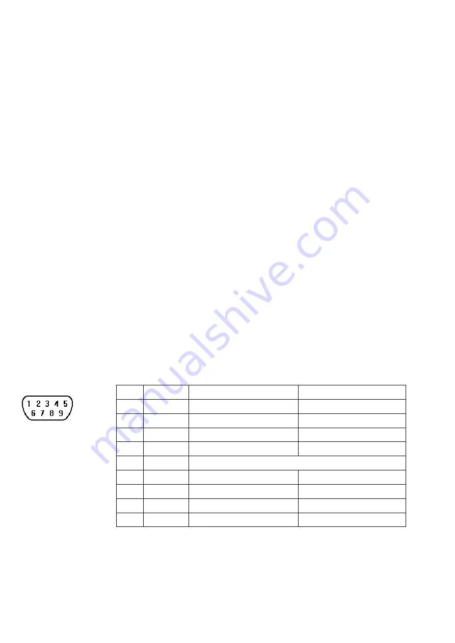
Pin assignment of the 9 Pin, Male, SUB-D, COM1 [RS-232] and COM2 [RS-232] Port. 


Pin Designations 


COM1 [RS-232] 
COM2 [RS-232]


Pin#  Symbol 

COM1 [RS232] 

COM2 [RS232] 

Not used 


RxD 

Received Data 


TxD 

Transmitted Data 


TxD 


Transmitted Data 

GND 

Signal Ground 

RxD 


Received Data 

RTS 

Ready to send output 


CTS 

Clear to send input 


Not used 


2.3.2 Connector COM1[RS485] , COM3[RS485] and COM3[RS232] 

The 9 Pin, Female, SUB-D, COM1 [RS-485], COM3 [RS-485] and COM3 [RS-232] Port on the back 

of the unit is the RS-232 and RS485/422 communications port for connecting to a controller.   


Summary of Contents for MT-8150X

Page 1: ...0 Series has been tested to conform to European CE requirements This means that the circuitry is designed to resist the effects of electrical noise This does not guarantee noise immunity in severe cases Proper wire routing and grounding will insure proper operation Mechanical Environment Avoid installing units in environments where severe mechanical vibration or shocks are present 2 0 Installation...

Page 2: ...hat the operating limits are followed See Specifications Do not operate the unit in areas subject to explosion hazards due to flammable gases vapors or dusts The unit should not be installed where fast temperature variations and or high humidity are present This will cause condensation of water in the device Do not install these terminals in environments where have inflammable gases 2 2 Power Conn...

Page 3: ...an earth connection should be made from the power supply return point to the central star earth point Ground conductors should be as short and as large in size as possible The conductors must always be large enough to carry the maximum short circuit current of the path being considered Ground conductors should be connected to a tree from a central star earth ground point This ensures that no groun...

Page 4: ... programs are changed while the equipment is in operation The ICS 3 304 81 Safety Recommendations are reproduced by permission of the National Electrical Manufacturers Association from NEMA ICS 3 304 2 3 Communications Connections The ports as you look at the back of the case are the ports for connecting to a PLC or some external device Controller Connectors 2 3 1 Connector COM1 RS232 COM2 RS232 C...

Page 5: ...e Com1 RS232 RS485 2wire 4wire Com3 RS232 RS485 mode can be set by CECP In the Windows CE desktop 2 3 3 USB Host port USB 2 0 Host interface supports USB mouse keyboard USB Flash Drive and printer While using external hard drive please use external power supply Do not use USB port to charge external device 2 3 4 Connecter Wire MT8 Ethernet RZC045120 Direct connect Ethernet crossover cable MT8000 E...

Page 6: ...MT 600 8000 Series EMC Directive 2004 108 EC electromagnetic emissions and immunity UL508 ISBN 0 7629 0404 6 machine safety for use in Pollution Degree 2 Environment MT600 products will be CE marked to indicate compliance with the EMC Directive The MT 600 8000 Series has been designed to operate satisfactorily in electromagnetic noise immunity and without emitting high levels of electrical noise i...

Page 7: ...t Support SD SDHC RTC Built in CR2032 3V lithium battery General Specification Input Power 24 10 VDC 21 6 26 4VDC Power Isolator Inside Power Consumption 1 6 A 24VDC Isolated Power Supply Built in CE FCC Complies with EN 55022 1998 A1 2000 A2 2003 Class A EN 61000 3 2 2000 A2 2005 EN 61000 3 3 1995 A1 2001 EN 55024 1998 A1 2001 A2 2003 Voltage resistance 500VAC 1 min Isolation resistance Exceed 50...

Page 8: ...M3 RS485 COM3 RS232 COM1 RS232 COM2 RS232 m j VIP1 VIP2 a IDE interface DOM slot i USB Host port x 2 b Mini USB j Ethernet port 10 100 Base T c Fuse k Com1 RS485 Com3 RS485 Com3 RS232 d Power connector l Com1 RS232 Com2 RS232 e Reset button m SD CARD SLOT f VESA 75mm screw holes n Video Input Port x 2 V2 Only g Mic In h Line Out Cutout Dimensions MT615X MT8150X 352mm 13 86 Wx279mm 10 98 H GME8615V...

Reviews: