The Weir Group PLC
Weir Industrial Gateway setup guide rev 0.5
Copyright © Weir Minerals Australia Ltd 2017. Commercial in Confidence. All rights reserved.
Page
25
of
46
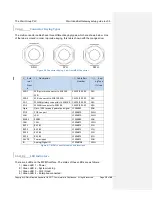
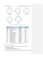
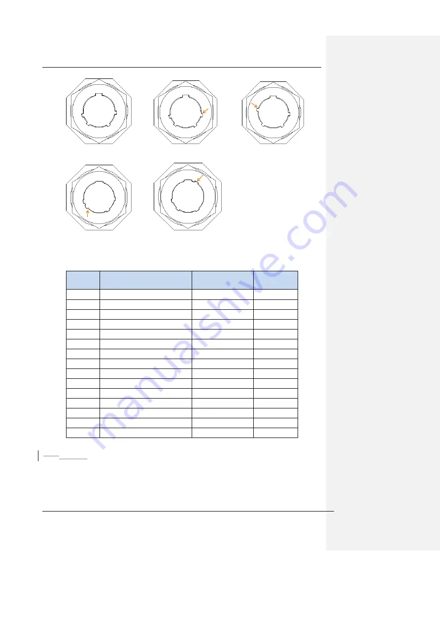
SNH
SYH
SWH
SXH
SZH
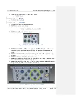
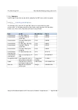
Figure 11-5 Connector Keying, View from RSP Connector
External
Name
Description
Cable Part
Number
Keying Type
If Used
24V Aux
Auxiliary 24V power input
LFS04897
SXH
RS485
RS485/RS232 input
LFS04880
SNH
POE
POE port
LFS04870
SWH
CAN
Can bus port
LFS04872
SWH
MPM
Main MPM connector
LFS04873
SYH
AO0
Analog Output Bank 0
No Application
SZH
AI0
Analog Input Bank 0
LFS05179
SNH
AI1
Analog Input Bank 1
LFS05179
SNH
DO0
Digital Output Bank 0
LFS04879
SNH
DO1
Digital output Bank 1
LFS04879
SNH
DI0
Digital Input Bank 0
LFS04878
SWH
DI1
Digital Input Bank 1
LFS04878
SWH
DI2
Digital Input Bank 2
LFS04878
SWH
AI2
Analog input bank 2
LFS04877
SNH
AI3
Analog input bank 3
LFS04877
SNH
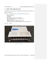
Figure 11-6 RSP Connector port descriptions
12.411.4
LED Indicators
There are 4 LEDs on the MPM front face. The status of these LEDs are as follows::
5.) Green LED 1
– Power
6.) Green LED 2
– System running
7.) Green LED 3
– MPM Communication Status

