The Weir Group PLC
Weir Industrial Gateway setup guide rev 0.5
Copyright © Weir Minerals Australia Ltd 2017. Commercial in Confidence. All rights reserved.
Page
31
of
46
13.212.2
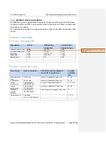
List of Junction Boxes
Description
Part#
RSP cable(s)
Sensor cables supported
4 Channel AI
4_AnalogIn_JB
32 <-> 24 pin (part# TBD)
32 <-> 32 pin (part# TBD)
All single channel analog
8 Channel AI
8_AnalogIn_JB
32 <-> 24 pin (part# TBD)
32 <-> 32 pin (part# TBD)
All single channel analog
4 Tri + 4 GP AI
4Tri-4GP_AnalogIn_JB
32 <-> 32 pin (part# TBD)
2 cables required
4 x Tri-axial Accelero 4 x
single channel analog
3 Tri + 7 GP AI
3Tri_7GP_AnalogIn_JB
32 <-> 32 pin (part# TBD)
2 cables required
3 x Tri-axial Accelero 7 x
single channel analog
4 x DI
4_DigIn_JB
19 <->19 pin (part# TBD)
IndProx_8_DigitalInJB_Cable_XXm
8 x DI
8_DigIn_JB
19 <->19 pin (part# TBD)
IndProx_8_DigitalInJB_Cable_XXm
4 x DO
4_DigOut_JB
19 <->19 pin (part# TBD)
TBD
8 x DO
8_DigOut_JB
19 <->19 pin (part# TBD)
TBD
2 x AO
TBD
13.312.3
Installation
This section covers the generic installation process for the junction boxes.
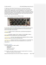
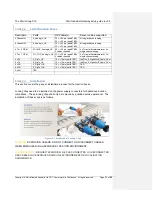
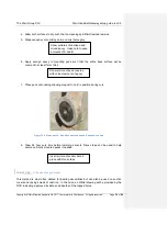
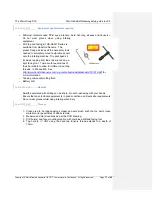
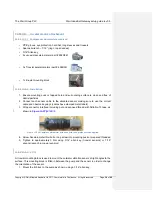
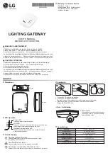
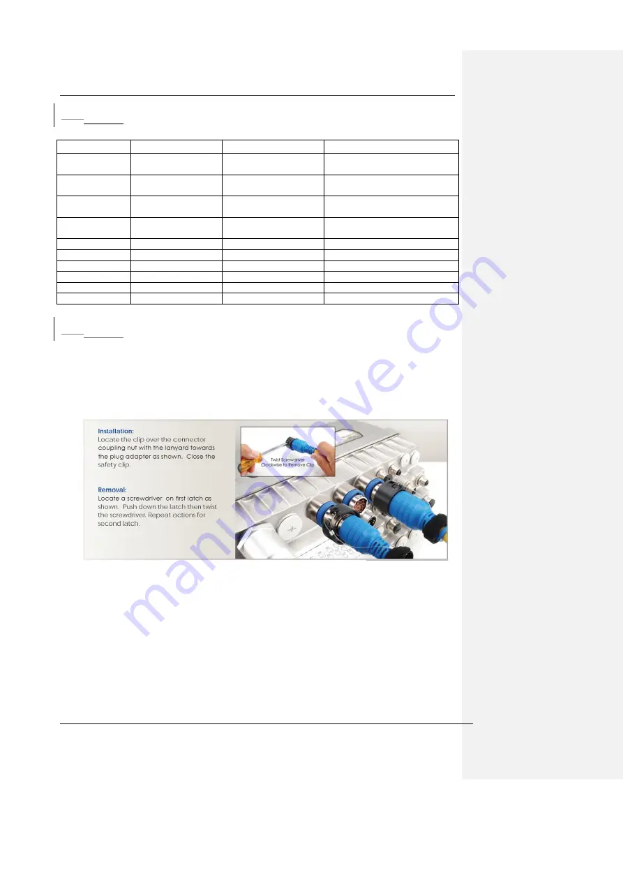
Locking clips need to be installed on the power supply connectors for hazardous location
compliance. These locking clips shall only be removed by qualified service personnel. The
installation of these clips is as follows:
Figure 12-1 Installation of Locking Clips
WARNING
: EXPLOSION HAZARD. DO NOT CONNECT OR DISCONNECT CABLES
WHEN ENERGIZED IN A HAZARDOUS LOCATION ENVIRONMENT.
AVERTISSEMENT
: RISQUE D'EXPLOSION. NE PAS CONNECTER OU DÉCONNECTER
DES CÂBLES QUI ENERGISES DANS UN ENVIRONNEMENT DE LOCALISATION
DANGEREUSE.

