The Weir Group PLC
Weir Industrial Gateway setup guide rev 0.5
Copyright © Weir Minerals Australia Ltd 2017. Commercial in Confidence. All rights reserved.
Page
41
of
46
Replace image with new hardware
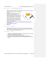
Figure 13-8 Gland water sensor installation
14.813.8
Speed
–
Proximity sensor
14.8.113.8.1
Equipment and materials required
• Spanner/wrench – as required for particular mounting bracket and bearing assembly
• Fasteners
• 1x Speed Sensor (Part # 872C-N8NP12-04)
• Mounting bracket (dwg xxxxx)
• Target bracket (dwg xxxxxx
• Protective tape – Nitto Self-fusing Butyl Rubber Tape – No.15
• Gap measurement tool
• Speed sensor integrity check tool
14.8.213.8.2
Hazards
-
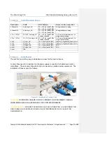
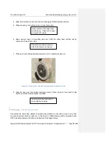
The Pump Shaft speed sensor is mounted off the motor end of the bearing assembly.
-
To install the speed sensor the motor must be turned off and tagged out for safety
-
There may also be pinch or crush hazards when/if the shaft is rotated during the
alignment process
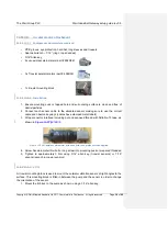
Figure 13-9 Speed sensor mount example (new picture required)


