Installation and operating instruction
Oil burner WL5-PB-H purflam®
3 Product description
83242002 1/2019-03 La
10-76
3.3 Function
3.3.1 Air supply
Fan with variable speed drive
The fan supplies the air from the air inlet via the intake connection to the mixing
head. The fan speed is set using a potentiometer. This matches the air quantity to
the mixing pressure required for combustion.
Air damper with nozzle solenoid (optional)
When the fan starts, the nozzle solenoid opens the air damper. At burner shutdown
the air damper closes automatically. At burner shutdown the air dampers close
automatically.
Air pressure switch
The air pressure switch monitors the fan pressure. If the fan pressure is insufficient,
the combustion manager initiates a lockout.
An additional air pressure switch is not required for ducted air intake.
3.3.2 Oil supply
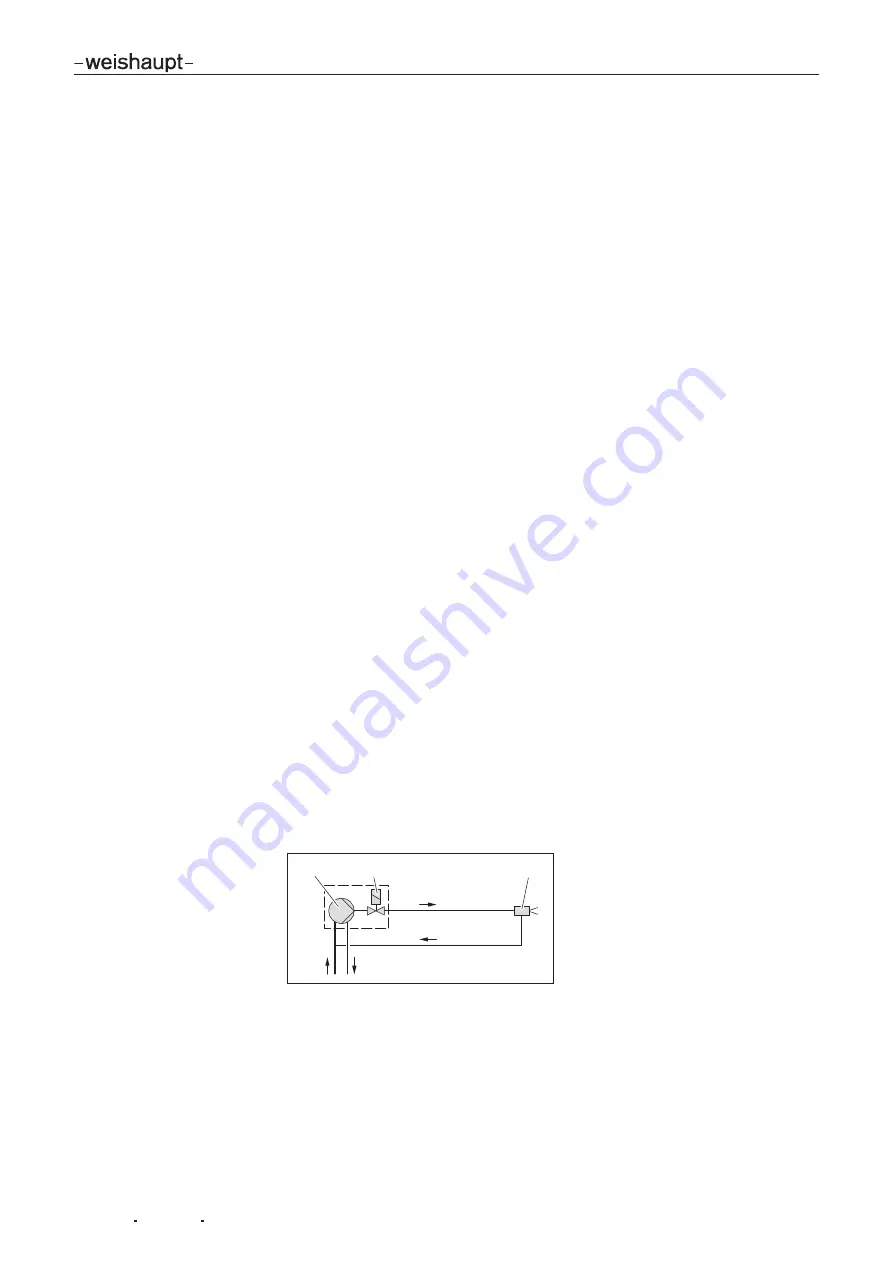
Oil pump
The pump draws the oil through the supply line and carries it under pressure to the
oil nozzle. The pressure regulating valve keeps the oil pressure constant.
A solenoid valve opens and closes the oil supply to the nozzle. The pressure regu-
lating valve and solenoid valve are integrated into the pump.
Nozzle head with nozzle shut off
The nozzle shut off is integrated in the nozzle head. It prevents oil leaks after shut-
down.
Heat exchanger
The heat exchanger in the nozzle assembly heats the oil. At an oil temperature of
approx. 45 °C the temperature switch releases the burner start.
Sequence diagram
1
2
3
1
Oil pump on burner
2
Solenoid valve on the oil pump
3
Nozzle head with nozzle shut off and nozzle


