background image


Assembly and installation instructions


Circulation station WHI circuload 9 #1; Circulation station WHI circuload 9 #2


  9 Spare parts 


83288702 

▪ 

1/2014-02 

▪ 

Ext. PAW 

22-24 


9.2


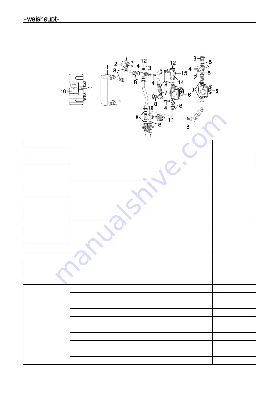
Spare parts list WHI circuload 9 #2 (40900015162) 


Position number 

Spare part 

-w-Part number 

1


Plate heat exchanger Swep IC10T/30 

40900015387


2


Piston valve DN 20 G1A with drain 

40900015092


3


Non return valve DN 20 G1Fl.xG1A 

40900015227


4


Temperature sensor NTC 5K G¼A 

40900015027


5


Circulation pump UPM2 15-75 CIL 

601856


6


Circulation pump UPM2 15-75 LowFlow 

601852


7


Seal 17 x 24 x 2 (¾") AFM34 

48002002857


8


Seal 21 x 30 x 2 (1") AFM34 

48002002847


9


Seal 21 x 30 x 2 (1") EPDM 90 

40900015167


10


Solar controller WRSol 2.1 V2.0 

660327


11


Name plate WHI circuload 9 #2 

40900015417


12


Bleed plug G½A 

40900015277


13


Reducing piece G½A x G¼I 

40900015267


14


FlowRotor DN 25 90 degrees, impulse meter 2-50 l/min 

40900015572


15


Hall sensor with LED connection cable 

48002002867


16


Three way valve DN 20 Kvs 5.0 G1A / PN16 

40900015367


17


Thermostatic head for three way valve 40-70 °C, white, M30x1.5 

40900015377


Not shown in drawing 

Seal 36 x 49 x 2 (1¾") AFM34 

40900015397


Thermo handle -weishaupt- 

48002003132


Closing plug with O ring G¼A 

40900015107 

Temperature sensor NTC 5K ZTF 222.2 

660228


Plug fuse connection cable PWM 

48002002627


Connection cable 2500 mm for Hall sensor 

48002003127


Connection cable PWM 2500 mm long 

48002002617


Pump cable 3 x 0.75  2500 mm long 

48002002607


Plug cable temperature sensor 2500 mm 

40900015037


Outlet valve with O ring G¼A 

40900015097


Summary of Contents for WHI circuload 9 1

Page 1: ...Mounting and operating instructions Circulation station WHI circuload 9 1 Circulation station WHI circuload 9 2 83288702 1 2014 02 ...

Page 2: ......

Page 3: ...e circulation stations 9 3 3 Technical Data Pumps 10 3 4 PWM input signal solar profile 10 3 5 Hydraulilc performance data 11 4 Dimensioning and Planning 12 5 Installation 14 5 1 Assembly 14 5 2 Connection 15 5 3 Controller connection 16 5 4 Electrical connection of the solar controller WRSol2 1 16 6 Operation 16 7 Commissioning 17 7 1 Filling the primary circuit 18 7 2 Commissioning the controlle...

Page 4: ...led personnel It must be observed by anyone working on the machine Work on the machine may only be performed by persons that have received the required training or instruction Persons with restricted physical sensory or mental abilities may work on the machine if supervised or instructed by an authorized person Children may not play with the machine 1 2 Warranty and liability Warranty and liabilit...

Page 5: ...ulations of the employers liability insurance association Instructions and safety instructions mentioned in these instructions CAUTION Risk of burns The valves and fittings and the pumps can become heated up to more than 95 C during operation The insulation shell must remain closed during operation NOTICE Material damage due to mineral oils Mineral oil products cause permanent damage in the materi...

Page 6: ...ctrical connection When performing any work on live parts Observe the accident prevention regulations BGV A3 and local regulations Use tools according to EN 60900 2 5 Structural modifications Conversion measures are only allowed after prior approval in writing by the Max Weishaupt GmbH Additional components may only be installed if they were not tested together with the machine Use only Weishaupt ...

Page 7: ... and on the heating return FlowRotor with Hall sensor and temperature sensor on the heating supply only WHI circuload 9 2 Lockable primary pump Vent plug on the heat exchanger Thermal mixing valve for limiting the circulation temperature Connections 1 Secondary side circulation outlet 2 Primary side supply from buffer tank 3 Primary side return to buffer tank 4 Secondary side circulation inlet Equ...

Page 8: ... or WHI load modules The direct supply of the modules with hot water from the buffer tank guarantees an energy and cost optimised operation of the circulation system The return line of the circuload modules can be integrated into the buffer tank tanks independent of the return line of the WHI freshaqua or WHI load modules A mixture of hot and cold water is therefore reduced to a minimum so that th...

Page 9: ...900 l h secondary 1550 l h Operating temperature sensors 25 C to 120 C Equipment Primary pump High efficiency pump with PWM control 3 70 W Secondary pump High efficiency pump with PWM control 3 70 W Heat exchanger 30 plates Flow rate sensor Primary FlowRotor measuring range 2 50 l min 55 pulses litre Temperature sensor primary 1 x NTC 5K secondary 2 x NTC 5K primary secondary 2 x NTC 5K each Check...

Page 10: ...tions 1 male thread Protection class IP 44 Max pressure 1 0 MPa 10 bars Max temperature 95 C TF 95 I 1 1 0 04 0 52 A P1 3 70 W Use in WHI circuload 9 1 Prim Sec WHI circuload 9 2 Prim Sec Prim Primary side accumulator circuit Sec Secondary side circulation 3 4 PWM input signal solar profile PWM input signal Pump status 6 Standby 6 8 Hysteresis 9 15 Min speed 16 90 Linear increase in speed from rpm...

Page 11: ...irculation station WHI circuload 9 2 3 Product description 83288702 1 2014 02 Ext PAW 11 24 3 5 Hydraulilc performance data WHI circuload 9 1 or WHI circuload 9 2 Heating UPM2 15 75 LowFlow Circulation UPM2 15 75 CIL Flow rate l h Residual delivery pressure or pressure drop mbars ...

Page 12: ...certain requirements Take a little time for the planning before the assembly Assembly example 1 circulation station from standby buffer When using the WHI circuload in combination with a standby buffer hydraulic version 38 must be set in the controller Please note Due to their construction the WHI circuload modules reduce the precipitation of scale in the heat exchanger For systems with a high tot...

Page 13: ...y example 2 circulation station from pre heat buffer The circulation stations are preset in the factory for using the pre heat buffer hydraulic version 39 on the controller You can obtain further information on this in the enclosed controller manual or the planning documents for large solar systems Circulation station Fresh water station Solar heat storage device Heat generator WAS ...

Page 14: ... and safety equipment must be guaranteed at all times during operation If tapping points are connected to the same network as the circulation station in which pressure surges are possible e g flushing valves washing machines or dishwashers we recommend the installation of water hammer dampers near the device causing the pressure surges WARNING Risk to life and limb due to electric shock Prior to p...

Page 15: ... about 40 mm protrudes from the wall 5 Pull off the front shell 6 Hang the circulation station on the screws and insert the screws at the bottom Tighten the screws so that the insulation on the sides rest against the wall 5 2 Connection Pipe the circulation station with the system according to the diagram below Pipe gap from the wall secondary 107 mm 1 Secondary side circulation outlet connection ...

Page 16: ...scription Execution L N 230V Mains connection 230 V on site 1 N PZWP Primary circuit pump prewired 2 N PZW Secondary circuit pump prewired 11 TZW Secondary circuit return sensor prewired 12 TZWA Secondary circuit flow sensor prewired 16 TO1 Heat source temperature on site 17 PWM2 PWM control signal for secondary pump prewired 18 PWM1 PWM control signal for primary pump prewired 19 TPR Primary circ...

Page 17: ... with a check valve in ball valve J in order to prevent undesired gravity circulation The check valve must be opened for venting and flushing the system For this purpose turn ball valve J to position 45 The check valve is not in operation All ball valves and valves must be opened completely for operating the system position 0 Ball valve with integrated check valve Normal direction of flow in the p...

Page 18: ... injury Open the manual air vent slowly and at a safe distance With partially filled tank During the filling and flushing of the circulation station air can be vented using the manual air vents O and P 1 Open ball valves H and J slowly by turning them to the 45 position 2 Carefully open the manual air vents O and P using a square key and allow the air to escape 3 Close manual air vents O and P 4 A...

Page 19: ...39 The pre setting must be adapted according to the system depending on the application 4 Carefully open and close the venting device on the check valve A 5 Select the manual mode for the secondary pump in the selection menu of the controller see controller manual Switch on the PWM signal of the secondary pump 100 6 Allow the secondary pump to run for 3 minutes 7 During this time vent the circulat...

Page 20: ...ew of the thermostat controller setting range Setting range on the thermostat controller Circulation temperature 5 50 C 6 60 C 7 70 C 7 5 Setting the pump revolution speed In order to increase the energy efficiency of the circulation station the revolution speed of the pumps must be adapted to the system specific conditions pressure drop in the pipework See the controller manual as to how the revo...

Page 21: ...7 9 Seal 21 x 30 x 2 1 EPDM 90 40900015167 10 Solar controller WRSol 2 1 V2 0 660327 11 Name plate WHI circuload 9 1 40900015407 12 Closing plug with O ring G A 40900015107 13 Cover screw G A 40900015257 14 Bleed plug G A 40900015277 15 Reducing piece G A x G I 40900015267 16 Three way valve DN 20 Kvs 5 0 G1A PN16 40900015367 17 Thermostatic head for three way valve 40 70 C white M30x1 5 409000153...

Page 22: ...r controller WRSol 2 1 V2 0 660327 11 Name plate WHI circuload 9 2 40900015417 12 Bleed plug G A 40900015277 13 Reducing piece G A x G I 40900015267 14 FlowRotor DN 25 90 degrees impulse meter 2 50 l min 40900015572 15 Hall sensor with LED connection cable 48002002867 16 Three way valve DN 20 Kvs 5 0 G1A PN16 40900015367 17 Thermostatic head for three way valve 40 70 C white M30x1 5 40900015377 No...

Page 23: ...y pipeline mm l m Secondary pipeline mm l m Other installations Have both circuits been correctly flushed and vented No air sounds in the pump Vented Are all shut off fittings open in the cold water and storage lines Open Is there a minimum pressure of 1 5 bars available on the primary side Checked Is there a minimum pressure of 2 5 bars available on the secondary side Checked Is a fault message s...

Page 24: ...ual fuel burners operate reliably Solar systems The stylish flat plate collectors are the ideal complement for any Weishaupt heating system They are suitable for solar water heating and for combined heating support With versions for on roof in roof and flat roof installations solar energy can be utilised on almost any roof multiflam Burners up to 17 000 kW This innovative Weishaupt technology for ...

Reviews: