Assembly and installation instructions
Circulation station WHI circuload 9 #1; Circulation station WHI circuload 9 #2
83288702
▪
1/2014-02
▪
Ext. PAW
15-24
1.
Determine the installation location of the circulation station near to
the buffer tank. With longer connecting lines, the transfer capacity
is reduced due to higher pressure losses.
2.
Transfer the dimensions for the drill holes onto the wall.
3.
Drill holes and insert the enclosed wall plugs. Make sure that the
ground has sufficient load-carrying capacity.
4.
Screw in the top screw into the plug until about 40 mm protrudes
from the wall.
5.
Pull off the front shell.
6.
Hang the circulation station on the screws and insert the screws at
the bottom. Tighten the screws so that the insulation on the sides
rest against the wall.
5.2
Connection
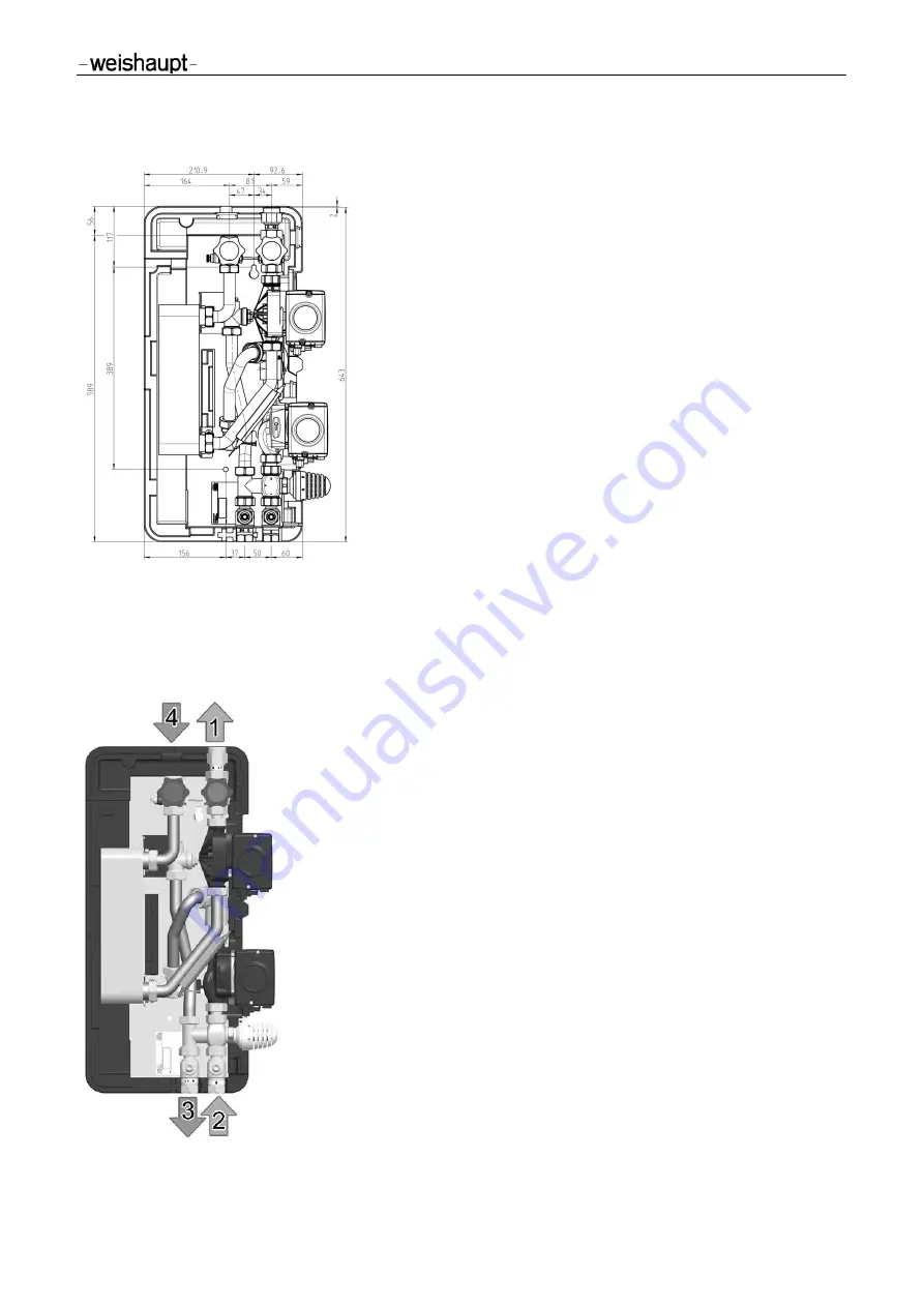
Pipe the circulation station with the system according to the diagram below.
Pipe gap from the wall
(secondary) = 107 mm
1
Secondary side:
circulation outlet
connection 1" male thread, flat sealing
2
Primary side:
supply from buffer tank,
¾" female thread,
piping
minimum DN 20, 22 x 1 mm,
recommended DN 25, 28 x 1.5 mm
3
Primary side:
return to buffer tank,
¾" female thread,
piping
minimum DN 20, 22 x 1 mm,
recommended DN 25, 28 x 1.5 mm
4
Secondary side:
circulation inlet
connection 1" male thread, flat sealing
Pipe gap from the wall
(primary) = 67 mm
Summary of Contents for WHI circuload 9 1
Page 2: ......


