Installation and operating instruction
Oil burner WL40/1-A Z-1LN-A
13 Spares
83319702 1/2020-10 La
99-116
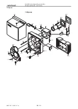
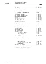
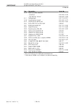
Pos.
Description
Order No.
1.01
Cover
241 400 01 112
1.02
Screw M8 x 16 DIN 7991
404 412
1.03
Burner housing
241 400 01 447
1.04
Intake housing complete
241 400 01 082
– Screw 4 x 22 Torx-Plus Remform
409 307
1.05
Hanging bolt
241 400 01 327
1.06
Grommet for oil hose
241 400 01 177
1.07
Grommet for connection cable
241 200 01 247
1.08
Mounting bracket for cover
241 400 01 207
1.09
Clamp
241 400 01 357
1.10
Cover burner housing
241 400 01 387
1.11
Screw M8 burner housing
241 400 01 257
1.12
Housing cover
241 400 01 457
1.13
Screw G⅛A DIN 908
409 004
1.14
Sealing ring 10 x 13.5 x 1.5 DIN 7603
441 033
1.15
Bracket for oil hose
241 400 01 367
1.16
Intermediate flange
241 400 01 427
1.17
Threaded socket R⅛ WES6
453 010
1.18
Protective cap DN 6 SELF 50/2 CF
232 300 01 047
1.19
Pin M12 x 118
241 400 01 267
1.20
Joint 80 x 64.75
241 400 01 067
1.21
Joint 106.9 x 120
241 400 01 077
1.22
Burner flange
241 400 01 437
– Screw M10 x 35 DIN 912
402 600
– Washer A10.5 DIN 125
430 603
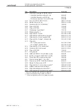
1.23
Flange gasket 8 x 238.5 x 238.5
– Standard
241 400 01 147
– for rotated by 180°
240 410 00 017
1.24
Stay bolt M10 x 120 burner flange
241 400 01 247
1.25
Flame tube W40/1LN
– Standard
241 400 14 032
– extended by 100 mm*
240 400 14 052
– Screw M5 x 12 Combi-Torx-Plus 20IP
409 247
– Washer 5.5 x 12 oval
241 400 14 077
1.26
Flame sensor RAR9**
240 310 12 222
1.27
Flange for RAR9**
600 602
* Only in conjunction with combustion head extension.
** Only in conjunction with continuous operation.


