Installation and operating instruction
Oil burner WL40/1-A Z-1LN-A
3 Product description
83319702 1/2020-10 La
12-116
3.3.2 Oil supply
Oil pump
The pump draws the oil through the supply line and carries it under pressure to the
oil nozzle. The pressure regulating valve keeps the oil pressure constant.
Solenoid valves
The solenoid valves open and close the oil supply.
For ignition, the combustion manager opens the stage 1 solenoid valve and the
safety solenoid valve. Stage 2 solenoid valve opens or closes depending on heat
demand.
Minimum oil pressure switch (optional)
Depending on the burner application, optional equipment may be required for op-
timum operation [ch. 12.3].
The minimum oil pressure switch monitors the pump pressure in the supply. If the
preset pressure is not achieved, the combustion manager initiates a lockout.
Nozzle head with nozzle shut off
The nozzle shut off is integrated in the nozzle head. It prevents oil leaks after shut-
down.
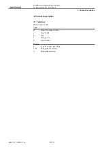
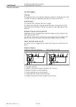
Sequence diagram
Standard / continuous operation
with oil pressure switch
P
P
1
2
5
4
3
6
1
2
5
4 4
3
6
1
Oil pump on burner
2
Stage 1 solenoid valve (normally closed) on the oil pump
3
Minimum oil pressure switch (optional)
4
Safety solenoid valve (normally closed)
5
Nozzle head with nozzle shut off and nozzle
6
Stage 2 solenoid valve (normally open) on the oil pump


