background image

5. THE USAGE OF KEYS

5.1 The PRINT key

The printer should connect with the host and turn on the power supply, at first

press the PAUSE key to pause the machine (The LED is in red); the printer will

print the data after pressing the printer key again.

Press the PAUSE key once more if need to continue the test or stop the print.

5.2 The SETTING key

You need to enter the setting menu by usage the SETTING key when setting

the parameters.

After setting the parameters and press the SETTING key again, then enter the

next setting menu.

5.3 The VALUE key ↓

You can set the lower value by pressing the value key ↓.

5.4 The VALUE key ↑

You can set the higher value by pressing the value key

↑.

5.5 The BEAT MODE key

In testing state, then press the beat number key one time; you can manually

adjust the bear number by pressing the VALUE key ↑ ↓. The instrument starts

to test as the selected beat number immediately.

Summary of Contents for 60003

Page 1: ...he VALUE key 7 5 4 The VALUE key 7 5 5 The BEAT MODE key 7 5 6 The SIG GAIN key 8 5 7 The SIG GAIN key 8 5 8 The MEAS TIME key 8 5 9 The SOUND key 8 5 10 The PRINT key 8 5 11 The CURSOR keys 8 6 THE PARAMETER 9 6 1 The beat number Frequency number Manual and Automatic selection 9 6 2 The lift angle 9 6 3 The test period 9 7 THE TECHNICAL DATA 10 8 THE INSTRUMENT MATAINCE 11 8 1 There is no reactio...

Page 2: ...fferent watch 3 The instrument can automatic calculate and display the day rate amplitude and beat error 4 The instrument can automatic tests the common beat watches otherwise you can manually select for the special ones 5 The instrument can select the test period of 2S 4S 8S 12S 20S 30S 60S which can calculate the average value of corresponding period 6 Six kinds of test orientation can be set th...

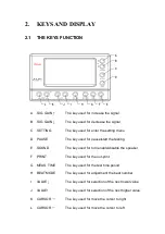
Page 3: ...d for pause start the testing E SOUND The key used for turn enable disable the speaker F PRINT The key used for the out print G MEAS TIME The key used for the test time period H BEAT MODE The key used for adjustment the beat number I VALUE The key used for selection of the next lower value J VALUE The key used for selection of the next higher value K CURSOR The key used for move the cursor to righ...

Page 4: ...y B AMPLITUDE Display of the amplitude in degrees C BEAT ERROR Display of the beat error in millisecond D GAIN Display of adjustment the signal intensity E STATUS Display of the time and running state F BEAT Display of the current beat value G PERIOD Display of the test period H LIFT Display of the degrees of lift angle I COLOR Display of the selected color J DISPLAY MODE Display of the selected d...

Page 5: ...uency calibration connector Just for the engineer use C The printer connector D The power supply connector Adaptation range for DC 12V 3 INSTALLATION 3 1 THE BASIC EQUIPMENT COMPONENTS A The test hosts B The microphone C The power cable D The user manual ...

Page 6: ...tlet Power supply voltage is 100 240V 3 2 2 THE MICROPHONE CONNECTION Connect the sensor plugs with the host sensor connector 3 2 3 THE PRINTR CONNECTION Connect the plug of thermal printer with the host interface The connection is unnecessary if no printer 4 OPERATION The instrument automatic start to work after power on some parameters set by the user don t store after power down and can be retu...

Page 7: ... You need to enter the setting menu by usage the SETTING key when setting the parameters After setting the parameters and press the SETTING key again then enter the next setting menu 5 3 The VALUE key You can set the lower value by pressing the value key 5 4 The VALUE key You can set the higher value by pressing the value key 5 5 The BEAT MODE key In testing state then press the beat number key on...

Page 8: ...12S The instrument starts to calculate the test result as the new period time after pressing the MEAS TIME key 5 9 The SOUND key User can enable or disable the key sound and the test sound 5 10 The PRINT key At first press the PAUSE key The LED is in red and then press the PRINT key you can print the test result if the printer is connect 5 11 The CURSOR keys Change the selected parameter item in t...

Page 9: ...anual select beat number as below 3600 6000 7200 7380 7440 7800 9000 9100 10800 11880 12000 12342 12480 12600 13320 13440 13500 14000 14040 14160 14200 14280 14400 14520 14580 14760 14850 15000 15360 15600 16200 16320 16800 17196 17258 17280 17786 17897 18000 18049 18514 19332 19440 19800 20160 20222 20944 21000 21031 21306 21600 25200 28800 32400 36000 43200 6 2 The lift angle Most of the movemen...

Page 10: ...mplitude doesn t exceed 330 in normal circumstances The period time of measurement average value 2S 4S 8S 12S 20S 30S 60S The Beat Error the frequency error measurement The value displays in the millisecond The resolution is 0 1 millisecond and the test range is 0 0 9 9 millisecond The amplitude The range is 30 70 and the default value is 52 The supply voltage The single 100 240V 0 1A 50 60Hz The ...

Page 11: ...nstrument can enter the test status after the sound of DI but it can t work after installing the sensor Check out whether the watch work or not and the amplitude is up 100 and make sure the watch crown can touch the sensor metal sheet 8 3 The LED signal is in red but the shown lines is scattered or appear many lines Maybe the beat number was wrong and adjusts the right beat number by manual select...

Reviews: