16-
6
Assembly and Commissioning
Risk of injury in case of unexpected movements of the machine. Disconnect the power supply during
all assembly and maintenance work and ensure the module is force-free!
6.1
Mounting
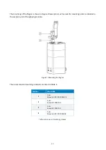
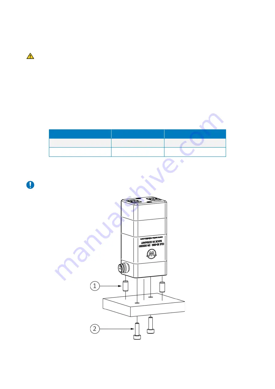
The dimensions of the threads and centering holes that can be used to mount the gripping module can be
found in the technical drawing. The following maximum torques and minimum screw-in depths must be ob-
served during assembly:
Thread
M2 base jaw (steel)
M3 housing (aluminium)
Max. Torque
0.3 Nm
0.7 Nm
Minimum screw-in depth
2 mm
3 mm
Table 5: Tightening torques for screws (min. strength class 8.8)
Maximum permissible unevenness of the mounting surface: 0.02 mm
Figure 6: Mounting the gripping module


