42-
9.11.1
Application Example External Gripping
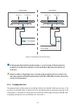
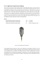
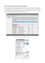
Figure 19 shows an example of external gripping with the CLG 30-006 gripping module. A syringe base body
is to be gripped and placed in a fixture. The syringe has a nominal diameter in the gripping area of 5 mm. The
gripper fingers were designed so that the nominal diameter corresponds to a jaw distance on the gripping
module of 5.5 mm. To ensure the reliability of the gripping process, a position tolerance of ±0.2 mm is spec-
ified. Due to the low weight of the workpiece, a gripping force of 15 N is specified. For the CLG 30-006, this
corresponds to a force setting of 50%. The part is parameterized as GRIP 0 of the gripping module. For this
purpose, the following parameters are set either via the configuration software of the IO-Link master or via
the GRIPLINK-U1 device configurator available from Weiss Robotics:
GRIP 0:
NO PART LIMIT(Index 0x60, Subindex 0x01):
120
(= 1.20 mm)
RELEASE LIMIT (Index 0x60, Subindex 0x02):
370
(= 3.70 mm)
Gripping force (index 0x60, subindex 0x03):
50
(= 50%, corresponds to 15 N)
Figure 19: Gripping example external gripping
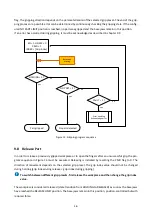
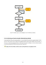
If the gripping module was restarted, it must first be referenced. In this example, a reference run to the
outside makes sense (factory setting). The gripping module is initialized via the program sequence in Figure
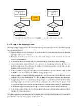
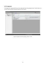
14. The gripping process is executed via the program sequences in Figure 15 (gripping part) and Figure
16(releasing part). Since GRIP 0 has been configured, the grip index 0 is to be used in the program sequence.
The gripping state is also visualized via the status display on the gripping module: In HOLDING state, the LED
HOLD lights up permanently.

