WEISS
Linear Assembly System LS 280 Mechanical System Documentation R05-2011
17/52
Product description
3.2 Function of the modules
3
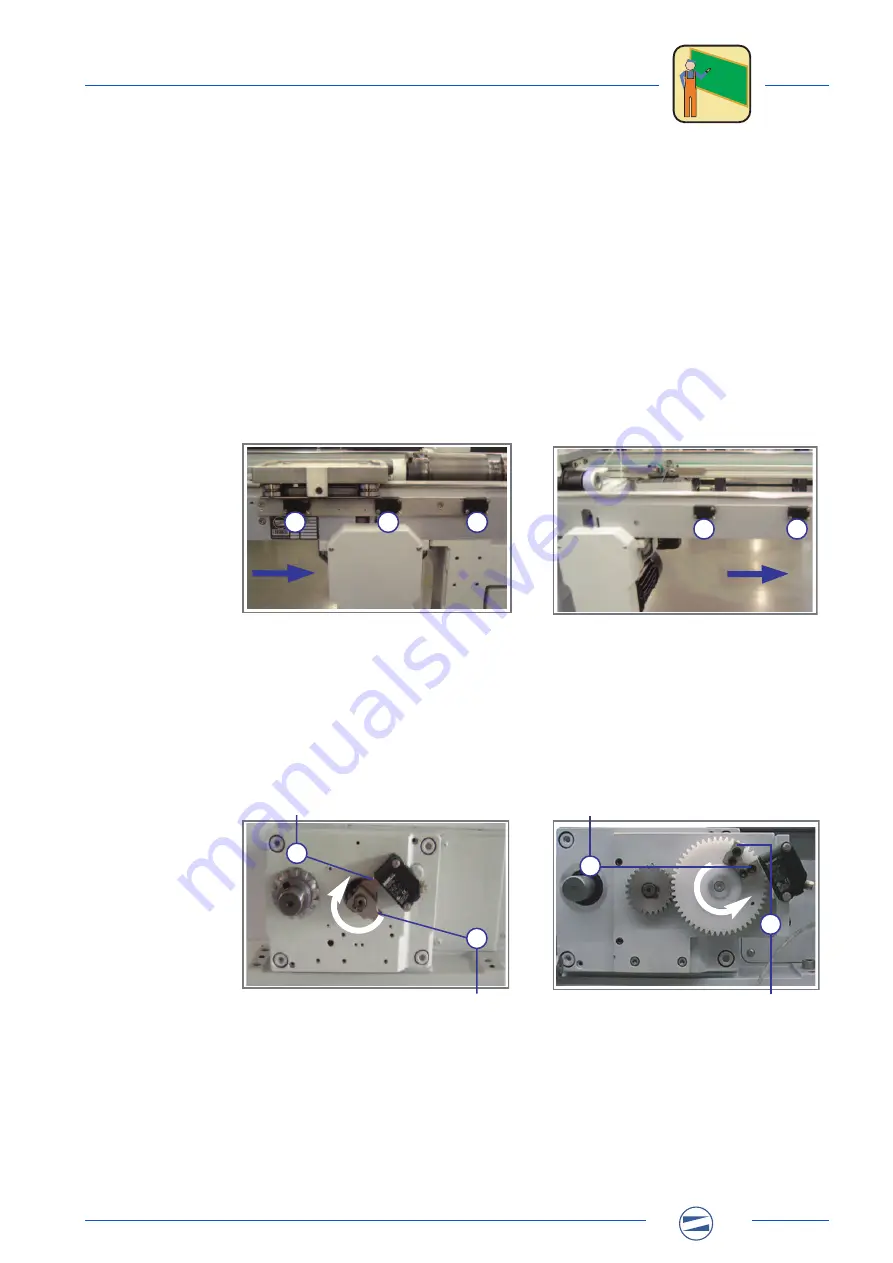
Sensors of the locking station:
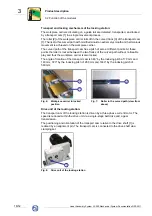
The movement sequence on the locking station is controlled via 7 sensors. Three sen-
sors are located on the ingoing belt upstream from the station, and two sensors are
located on the outgoing belt. The movement of the transport cam is controlled by 2
sensors on the drive unit.
Activation of the supplying ingoing belt:
To ensure a smooth and impact-free process the transport speed of the supplying belt is
speed-controlled with the aid of a frequency inverter. At the approach of a workpiece
carrier to the locking station the speed of the ingoing belt is reduced so that the entry into
the locking station is smooth and impact-free.
The stop ramp of the frequency inverter can be adjusted to the particular entry situation
and will be optimised depending on the payload on the workpiece carrier and the cycle
count of the system.
Activation of the locking station:
By switching on the drive motor the transport cam is rotated until the workpiece carriers
are further cycled one position. The drive motor of the locking station is activated by a
frequency inverter that moves the transport cam into the mechanically locked position in
a regulated manner.
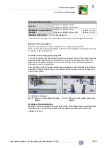
X = direction of transport
Fig. 9:
Sensors at the intake of the
locking station
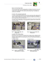
Fig. 10: Sensors at the outtake of the
locking station
"In Position" (back)
"In Position" (back)
"Pre-trigger" (front)
"Pre-trigger" (front)
Fig. 11: Sensors on the drive unit at
indexing pitch 70, 140, 280 mm
Fig. 12: Sensors on the drive unit at
indexing pitch 560 mm
X
1
2
3
X
1
2
1
2
2
1
i i i i i i i i i i i i i i i i i
i i i i i i i i i i i i i i i i i
i i i i i i i i i i i i i i i i i
i i i i i i i i i i i i i i i i i

