background image

Linear Assembly System LS 280 Mechanical System Documentation R05-2011

6/52

WEISS

Introduction

1.4 Laws / EC Directives / Norms

1

1.4

Laws / EC Directives / Norms

The machine is designed and constructed to conform to

applicable laws

Directive 2006/42/EG (Machinery Directive)

Low Voltage Directive, 2006/95/EC

EMC Directive 2004/108/EC

and the harmonised standards that we have cited

and meets state-of-the-art technological standards in terms of its construction.

1.5

EC Declaration

An EC Declaration as specified by Directive 2006/42/EC (Machinery Directive) is 
included with each machine at delivery.
The text of this EC Declaration is as follows:

WEISS GmbH Sondermaschinentechnik

Siemensstrasse 17
D-74722 Buchen

Declaration of incorporation of partly completed machinery

in accordance with EC Machinery Directive 2006/42/EC, Annex II B

Commissioning prohibition

We hereby declare the machine designated below with serial number LSXXXXXX is 
designed for installation in a different machine, or should be joined together with other 
machines to comprise a machine as specified in Directive 2006/42/EC.

Commissioning is prohibited until it has been determined that the machine in which the 
above-cited product will be installed satisfies the provisions of the EC Machinery 
Directive, and that a Declaration of Conformity in accordance with EC Machinery 
Directive 2006/42/EC, Annex II A has been issued.

1.6

System-dependant documentation

In addition to this operating manual, further documents are required to ensure safe ope-
ration of this machine. The specifications stated in these documents are to be observed.

Operating Manual LS 280 electrical system documentation

System-dependant documentation LS 280

Summary of Contents for LS 280

Page 1: ...Operating manual Linear Assembly System LS 280 Mechanical system documentation 980 240511001 EN 05 2011 ...

Page 2: ...74722 Buchen Service Tel 49 6281 52080 service weiss gmbh de www weiss gmbh de WEISS GmbH All rights in this document are the copyright of WEISSGmbH This document may not be copied or reproduced in whole or in part without the written permission of WEISS GmbH This document is only intended for the user of the product described and may not be passed on to third parties in particular competitors ...

Page 3: ...tallation 30 5 1 Safety during installation 30 5 2 Installation prerequisites 31 5 3 Installing the machine 32 5 4 Instructions on disposal of packaging material 36 6 Commissioning 37 6 1 Safety during commissioning 37 6 2 Initial commissioning 38 6 3 Recommissioning 38 7 Operation 39 7 1 Safety during operation 39 7 2 Operating the machine 39 7 3 Operating personnel workstations 39 8 Malfunctions...

Page 4: ...n the intake of the stop station 19 Sensors on the outtake of the stop station 19 Belt section with workpiece carrier train 20 Belt drive with motor without cover 20 Corner unit 180 21 Corner unit 90 21 Workpiece carrier train 22 Lubricating point in the guide rail 24 Lubricating point on the transport cam 24 Example of a type plate 25 Transporting modules in the packaging 27 Transporting modules ...

Page 5: ...ection to these It may only be used within the limitations defined in the order characteristics Commissioning is prohibited until conformity with Directive 2006 42 EC and all other applicable directives has been determined and confirmed for the facility in which the machine is installed Observance of the accompanying documentation and adherence to maintenance regulations are also component parts o...

Page 6: ...ompleted machinery in accordance with EC Machinery Directive 2006 42 EC Annex II B Commissioning prohibition We hereby declare the machine designated below with serial number LSXXXXXX is designed for installation in a different machine or should be joined together with other machines to comprise a machine as specified in Directive 2006 42 EC Commissioning is prohibited until it has been determined...

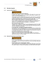
Page 7: ...h the machine Safety instructions in individual chapters should be observed 1 7 1 Explanation of safety instructions in this manual This manual contains instructions which you should observe for your personal safety and to avoid material damage Safety instructions for your personal safety are highlighted by a sign containing a warning triangle and signal word The associated text describes the haza...

Page 8: ...the second level of a list The book symbol before a section of text indicates additional applicable docu ments L The information symbol before a section of text marks an additional note or an important tip for use 1 7 3 Index of valid pages Pages of this operating manual including the title page 52 1 7 4 Figures The figures used are examples There may be differences between the illustrations and t...

Page 9: ... present required personal protective clothing is provided for and used by operating mainte nance and repair personnel the operating manual and all other applicable documentation is maintained at all times in legible condition and is accessible at the implementation site of the machine Ensure that all personnel who must execute activities tasks on the machine can access the operating manual at all...

Page 10: ...re not in the vicinity of the machine when tasks are being per formed supplemental to the operating manual the operating instructions as specified in labour protection legislation and work equipment use legislation are complied with the operator or supervisory personnel are informed in the event of malfunction required personal protective clothing is used The following work described in this opera...

Page 11: ... carrying out any work on these components the machine must first cool down sufficiently to avoid any risk of burning through contact Burn injuries will occur if there is contact with hot components Use of spare parts attachment of supplemental devices If spare parts are used or if supplemental devices are attached that are not approved by the manufacturer consequential damages can occur Only use ...

Page 12: ...ied electricians in compliance with the instructions in the operating manual for the electrical system docu mentation Electrical connections for the machine should only be disconnected or plugged in when the power supply is deactivated and secured against reactivation Touching energised components can lead to serious or fatal injuries A failure or malfunction of the control system can lead to inju...

Page 13: ...ain 2 Carrier plate 3 Central lubrication unit 7 Control packages 8 The assembly cells are controlled by remote control packages which are part and parcel of the machine Control packages as well as electrical components of the machine are described in operating manual LS 280 electrical system documentation Fig 1 Modules of the machine See order layout in the system dependant documentation LS 280 7...

Page 14: ...es Height adjustable mounting plate 4 Control cabinet Stationary support Fig 2 Assembly cell with locking station Locking station The locking station is available in two different versions a single locking station and a double locking station Both modules have the same design principle and contain the following components Steel transport cam with hardened cam path 1 Cam drive with gear transmissio...

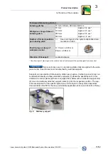
Page 15: ...3 move on stationary attached support rollers 4 into the respective position The sup ports are adjusted for the specific system see order layout in the system dependant documentation LS 280 for the max permissible application of force and transfer of force Fig 5 Stationary support Technical data locking station Indexing pitches 70 mm 140 mm 280 mm 560 mm Workpiece change times at indexing pitch 70...
Page 16: ...hout noticeable play and thus the workpiece carrier is also locked The angle of rotation of the transport cam is 360 by the indexing pitch of 70 mm and 140 mm 720 by the indexing pitch of 280 mm and 1440 by the indexing pitch of 560 mm Drive unit of the locking station The transport cam of the locking station is driven by a three phase current motor The speed is reduced within the drive unit via a...

Page 17: ...he stop ramp of the frequency inverter can be adjusted to the particular entry situation and will be optimised depending on the payload on the workpiece carrier and the cycle count of the system Activation of the locking station By switching on the drive motor the transport cam is rotated until the workpiece carriers are further cycled one position The drive motor of the locking station is activat...

Page 18: ...4 Accessories Floorboard 5 height adjustable Top support plate 6 Control cabinet X direction of transport Fig 13 Assembly cell with stop station as manual workstation Stop station The stop station is only used in conjunction with an autonomous belt section consisting of speed controlled ingoing belt and outgoing belt with constant speed The stop unit used herein is the holding point on a manual wo...

Page 19: ...mooth and impact free The stop ramp of the frequency inverter can be adjusted to the particular entry situation and will be optimised depending on the payload on the workpiece carrier and the cycle count of the system Activation of the stop station Opening the stop unit releases the workpiece carrier The release can be executed via an internal signal e g from a foot switch or it can also be execut...

Page 20: ... is 1200 mm and consists of a outgoing belt and an ingoing belt The band sections consist of the following components Steel guide rail with hardened and ground profile guide track Belt drive with three phase current motor Cast aluminium belt guide profile with VA slide rail Toothed transport belt AT5 PU belt Nylon coated Adjustable belt deflection rollers for adjusting belt tension Additional gear...

Page 21: ...ly run at a constant speed However if a short speed controlled ingoing belt into an locking station follows directly after the deflection the drive of the corner unit together with the belt drive are frequency controlled depending on cycle count and layout design The corner units consist of the following components Steel guide rail bend with hardened and ground profile guide track Cast aluminium b...

Page 22: ...continuous rail guide In the area of the belt sections and corner units catching is realised by friction via the sliding block Within the locking station the workpiece carriers are moved and precisely positioned by the transport cam through positive locking via a roller A workpiece carrier train consists of the following components Cast aluminium base body 1 Profile roller 2 Lateral roller 5 Plast...

Page 23: ...rkpiece carrier Technical data carrier plate Material St 52 chemically nickel plated Standard dimensions length x width x height 200 x 160 x 5 mm at indexing pitch 140 280 560 270 x 160 x 5 mm at indexing pitch 70 480 x 160 x 6 mm at indexing pitch 560 common carrier plate Different dimensions and versions on request Payload Product and device Approx 4 kg per carrier plate depending on the cycle c...

Page 24: ...he system The central lubrication unit is fastened on a mounting plate that is attached at an easily accessible point of the machine If the pre set lubricating interval is reached the pump receives a signal and builds up pressure of approximately 25 bar A pressure switch attached to the end of the main line signals that pressure has been built up successfully The pump is switched o the pressure dr...

Page 25: ...e respective module is specified The type plate shown is only intended as an example of a module and is not identical to the actual type plate on the product described A second type plate is included in the scope of delivery This second plate can be mounted at a clearly visible location on machine to allow viewing of data if the type plate fitted by the manufacturer is concealed by other structure...

Page 26: ...ntrol cabinet dimension 2400 mm Appr 425 kg Cell with two double locking stations and placement plates base frame withput control cabinet dimension 2400 mm Appr 590 kg Mounting plate lateral with console Appr 26 kg Belt section dimension 300 mm Appr 21 kg Belt section dimension 600 mm Appr 32 kg Belt section dimension 1200 mm Appr 53 kg Belt section dimension 1500 mm Appr 63 kg Belt section dimens...

Page 27: ... to the set up location can be execu ted by forklifts or the load can be attached to ropes and straps through an indoor crane 4 2 1 1 Machine with packaging To avoid tipping the transport crate the forks 1 of the forklift must be have a minimum length of 1 60 m When opening the transport crate the side panels should not fall inward Comply with the transport instructions 2 affixed on the transport ...

Page 28: ...ors or similar components Fig 26 Transporting modules without packaging Information about the weight of the modules is provided in chapter 3 3 5 4 3 Transportation damage The delivery should be inspected for damage immediately after receipt The contents of the delivery should be checked for damage if damage to the packaging is detected which could indicate damage to the contents Details of the sco...

Page 29: ...rs and no vibrations 2 years and longer with regular inspec tion Check for cleanless and machine damage during inspection Check that anticor rosion protection is unspoiled Tropical Asia Africa Central and South ameri ca Australia New Zealand except mo derate are as Packed in contai ners With moisture absorbers and humidity indicator sealed in film Protect against insect damage and mould forma tion...

Page 30: ...any installation personnel Wear personal protective clothing Crushing injuries When joining the modules together hands and fingers can get between stationary parts and moving parts Hands or fingers can be crushed Do not reach between the parts Wear protective gloves Injuries caused by incorrect installation Improper installation can cause consequential damage Work should only be assigned to auxili...

Page 31: ...must be statically measured to an adequate degree to ensure that it can support the operating weight of the machine The drives of the locking stations belt sections and corner units as well as the sen sors should remain easily accessible for maintenance work and the motor vents should have a minimum distance of 100 mm from other modules Base frame If delivered with base frames the base frames are ...

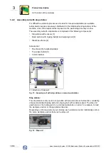
Page 32: ...arating points of the specific modules are numbered The machine must be set up in compliance with the information in this chapter 5 3 3 Align and connect modules 1 Set up modules in accordance with the layout and the markings 2 Align modules relative to each other In this process you must adjust the height as well as the horizontal position accordingly a machine water level is required Danger of i...

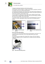
Page 33: ...ring modules must be supported during installation 1 Carefully introduce the positioning pins of the corner units into the receptacle bores of the counter rail 2 Bolt the corner unit to the guide rails In this process ensure that the joint location is free of contaminants 3 Removing the plug If a corner unit is packed separately for transport the plug for the vent screw of the drive unit must be r...

Page 34: ...ignment pins 3 of the guide rail bend 2 Unscrew the fixing screws 4 of the guide rail bend 3 Take off the guide rail bend 2 4 Carefully slide the new workpiece carrier train 1 onto the guide rail Pay attention to the direction of travel The sliding block must point toward the centre of the system Avoid tilting the profile rollers toward the guide 5 Fit the guide rail bend 2 In this process ensure ...

Page 35: ...piece carrier The carrier plate should only be placed on the base body with hand force Do not use a hammer If using a stationary support carrier plate and workpiece carrier are mar ked in pairs 1 Place the carrier plate 1 with mounted alignment pins 2 on the cast aluminium base plate 2 Press carrier plate into the receptacle bores with hand force Fig 32 Mounting the carrier plate 5 3 7 Stationary ...

Page 36: ... system is opened at the connection pieces of the piston distributors for transport of the individual cell modules 1 Insert opened main lubricating line Ø 8 mm 1 on the connecting pieces of the piston distributors 2 The open lines are kinked at the end to prevent the lubricant from escaping during transport Cut off the kinked hose end prior to connecting The connection for the outgoing lubricating...

Page 37: ...ent and emergency stop circuits are available and functioning correctly Prior to commissioning the machine check whether the drives are undamaged and not blocked all connections have been correctly established all tools and external parts have been removed all safety covers are correctly installed no other hazard sources are present The following should be checked during commissioning the drive mo...

Page 38: ...an cause injuries and material damage Recommis sioning should only be realised after it has been ascertained that the machine is in a functionally reliable condition and no risk emanate from it during operation A visual inspection of the machine should be conducted prior to re commissioning The following should be checked and ensured in this regard No damage is present on the machine No foreign ob...

Page 39: ...is being turned on and operated The operating instructions issued by the owner must be complied with 7 2 Operating the machine The machine is designed for integration in other machines in other incomplete machines or equipment or for connection to these Safe operation and control are the responsibility of the operator 7 3 Operating personnel workstations The operating personnel workstations are de...

Page 40: ...e You can contact our Customer Service from Monday to Friday between 08 00 and 17 00 at the Service number 49 0 6281 5208 0 or at service weiss gmbh de An answering machine will provide you with information outside of the abovementioned hours Injury of non authorised personnel Malfunctions should only be remedied by instructed personnel who have been trained in and are authorised to perform these ...

Page 41: ...with electric power supplies must be de energized Touching ener gised components can lead to serious or fatal injuries Injury of non authorised personnel Maintenance work should only be realised by instructed personnel who have been autho rised to perform these tasks The operating instructions laid down by the operator must be rigidly adhered to Injuries resulting from maintenance work which has n...

Page 42: ...on unit monthly During the inspection of the central lubrication system ensure that The lubricant tank is sufficiently filled If needed the tank must be filled with liquid grease NLGI class 00 A thin lubricating film must be present on the movement paths of the guide rails and transport cams The lubricant escapes at all lubricating points We recommend manually triggering a lubricating pulse on the...

Page 43: ...pitel 9 5 1 The drive motor must be checked for firm seat running noise and fouling and damage 9 3 5 Inspect the machine annually Inspect the entire machine for mechanical damage Cleanliness 9 3 6 Check for impermissible application of force After impermissible application of force on the transport system of an assembly cell the work pieces in question as well as the guide rails must be checked fo...

Page 44: ... the new motor on and screw in the four fixing screws for the motor flange but do not tighten them yet 8 Pull on the toothed belt 9 Tighten the four fixing screws for the motor flange 10 Connect the motor and check direction of rotation The direction of machine transport is counterclockwise If the motor has the wrong direction of travel the workpieces can collide Crushing injuries Reaching between...

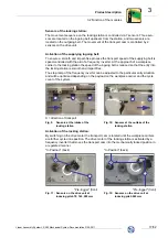
Page 45: ... remove them yet 3 Remove the cover 3 of the deflection rollers on the belt drive 4 Pull the belt drive 4 down far enough that the toothed belt 5 can be taken off above the deflection rollers 5 Insert new toothed belt and guide it around the deflection rollers 6 and the pinion 7 6 Re tighten the fixing screws 2 on the belt drive and mount the cover 3 of the deflection rollers 7 Screw in the fixing...

Page 46: ...ce carrier train 1 5 Carefully slide the new workpiece carrier train 1 onto the guide rail Pay attention to the direction of travel The sliding block must point toward the centre of the system Avoid tilting the profile rollers toward the guide 6 Fit the guide rail bend 2 In this process ensure that the joint location and the placement surface are free of contaminants 7 Strike in the alignment pins...

Page 47: ...ns in chapter 6 3 10 3 Dismantling and disposal Injuries can be cause during dismantling by falling components and by swinging or falling loads during transportation with lifting equipment The following points must be observed to avoid injuries and or environmental damage during dismantling and disposal Ensure that the correct tools and adequately dimensioned load lifting equipment are used and th...

Page 48: ...ined in the drive unit of the locking station as well as the corner unit must be drained prior dismantling the respective module and taken to an authorised oil collection point for environmentally responsible disposal The modules must subsequently be dismantled The individual parts must be recycled according to material type Materials that cannot be reused must be disposed of Information concernin...

Page 49: ...ate module WEISS article number and designation of the spare part according to the spare parts list Number of spare parts required Please send your spare parts order to WEISS GmbH Sondermaschinentechnik Siemensstraße 17 D 74722 Buchen Odw Tel 49 0 6281 5208 0 Fax 49 0 6281 5208 99 eMail service weiss gmbh de Internet http www weiss gmbh de All our representative addresses can be obtained on our we...

Page 50: ...Linear Assembly System LS 280 Mechanical System Documentation R05 2011 50 52 WEISS Appendix 12 1 Personal notes 12 12 Appendix 12 1 Personal notes 1 2 ...

Page 51: ...WEISS Linear Assembly System LS 280 Mechanical System Documentation R05 2011 51 52 Appendix 12 1 Personal notes 12 1 2 ...

Page 52: ...Weiss GmbH Sondermaschinentechnik Siemensstraße 17 D 74722 Buchen Telefon 49 0 6281 5208 0 Fax 49 0 6281 520899 info weiss gmbh de www weiss gmbh de WEISS ...

Reviews: