

WARNING! BE SURE TO DISCONNECT THE
ANGLE GRINDER FROM THE POWER SUPPLY
BEFORE ATTACHING OR REMOVING THE DISC OR
ATTACHMENT.
WARNING! MAKE SURE THAT A GRINDING
OR CUTTING DISC IS MOUNTED WITH THE LABEL
ON TOP OR FACING THE ANGLE GRINDER.
IF YOU ARE FITTING ANY OTHER KIND OF
ATTACHMENT, REFER TO ATTACHMENT FITMENT
INSTRUCTIONS. Northern Tool + Equipment WILL
NOT BE RESPONSIBLE FOR ANY DAMAGE OR
INJURY CAUSED DUE TO THE INCORRECT FITMENT
OF GRINDING OR CUTTING DISCS OR ANY OTHER
KIND OF ATTACHMENT. INCORRECT ATTACHMENTS
CAN CAUSE THE MOTOR TO BURN OUT,
GENERALLY DAMAGE THE TOOL OR CAUSE INJURY.
Attaching and removing the grinding disc provided:
• Inspect the disc before fitting and during use to ensure
it is not deformed or cracked.
• Ensure that the guard is fitted and at an angle which
ensures it is between you and the grinding disc. The
guard is there to protect you from dislodging objects
at the work piece and from accidental contact with the
disc, of your hand, fingers or other parts of yourself.
• Do not fit or use a grinding disc for cutting
applications – For cutting, use a cutting disc and ask
your hardware retailer for advice regarding the type of
material you wish to cut. Grinding discs are used for
grinding metal only.
• The grinding disc provided is not solid. It is made from
grit which is bonded together with reinforcement and
adhesives. It is always possible that a part of the disc
can dislodge and fly away from the tool at high
speed. This is why you must wear the appropriate
safety equipment (glasses, gloves and protective
clothing) described herein and follow all safety
instructions also described herein.
• Do not use any kind of attachment (discs or otherwise)
that has a diameter of greater than 4in. (100mm).
• Remove the outside retaining flange by hand if loose.
If tight, depress the spindle lock button at the top of
the gear box housing, rotate the spindle to locate the
lock position. Once the spindle is locked and cannot
be rotated, use the wrench supplied to loosen the
retaining flange.
• Remove the grinding disc from its envelope.
• Holding the angle grinder with the spindle facing
upwards, ensure the non threaded flange is on the
spindle and located correctly. The two machined flat
sections on one side of the non threaded flange must
face the angle grinder and locate in the appropriate
position on the spindle.
• Insert the grinding disc onto the angle grinder spindle
with the disc label facing the angle grinder. The hole
in the disc should be located onto the spindle. Ensure
that the hole in the disc locates and fits firmly into the
ring section of the non threaded flange.
• Screw the threaded flange onto the spindle with the
protruding ring section facing the angle grinder. This ring
section must locate with the hole in the grinding disc.
• Tighten the threaded flange by locking the spindle and
tighten with the spanner provided.
• Removal of the disc is conducted in reverse order
to the above.
• Regularly check that the disc retaining flange has
not loosened during use.
Note:
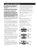
• When fitting a cutting disc, the ring section on outer
flanges should face away from the disc.
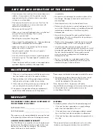
• When fitting the wire wheel, the ring section on
the outer flange should face into the wheel.
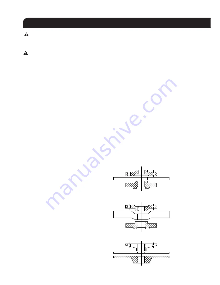
Fitting of Sanding Accessory:
• Thread backing wheel onto grinder first.
• Select the grit of paper that you wish to use.
• Place grit on wheel and then thread the paper
retaining nut on and tighten using spanner and
spindle lock.
ASSEMBLY AND INSTRUCTIONS
For use with cutting disc
Outer Flange
Inner Flange
For use with grinding disc and wire wheel
Outer Flange
Inner Flange
For use with sandpaper
Outer Flange
Inner Flange


