5.
ELECTRICAL
Install in accordance with local codes and/or
the National Electric Code ANSI/NFPA No.
70-1990 (USA) or the Canadian Electric Code
CSA Standard C22.1 (Canada). A separate
fused disconnect switch must be supplied and installed. The
kettle must be electrically grounded by the installer.
The electrical supply must match the power requirements
specified on the kettle's rating plate. The copper wiring must
be adequate to carry the required current at the rated
voltage.
Note: Maximum voltage for LVD (low voltage directive for
Europe) to be 440 volts for CE marked appliances.
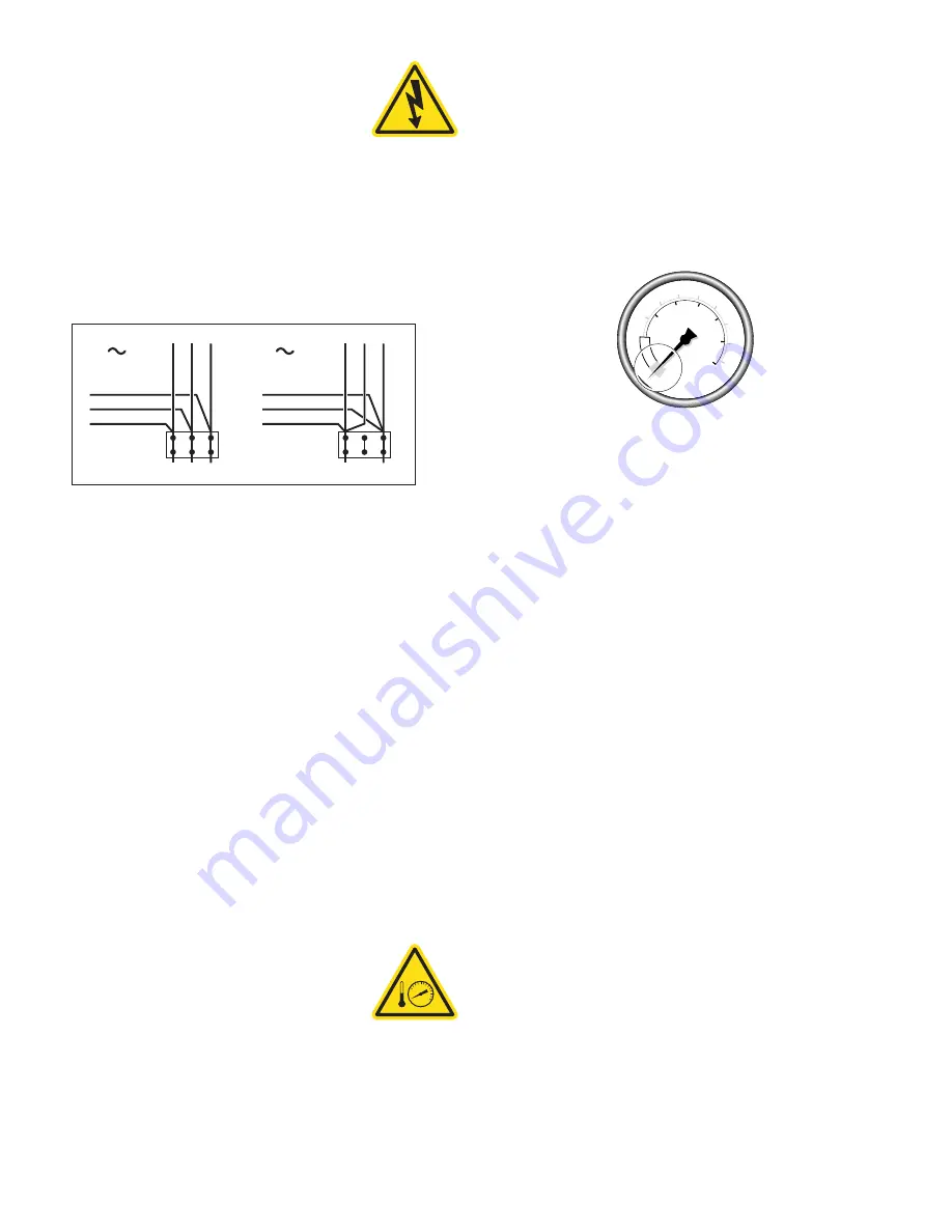
The kettle is wired for 3-phase operation at the factory. For
single phase operation, rewire the terminal block to that
shown in the above diagram.
Note: Ensure main power is turned off before connecting
wires.
Stationary Models
Remove the screws securing the dome-shaped service cover
underneath the kettle and remove the cover. A wiring diagram
is affixed to the inside of cover. Fasten permanent copper
wiring to the three-connection terminal block, Be sure to
connect ground wire to the separate ground terminal
connector (ground lug). Slide the cover's slot over the wiring
and secure the cover to kettle with the screws.
Tilting Models
First remove the handwheel by loosening the allen screw.
Then remove the two screws at the front and rear of the
console cover and remove the cover. A wiring diagram is
affixed to the underside of the console cover. Feed
permanent copper wiring through the cut-out in the bottom of
the console, and fasten to the three-connection terminal
block. Be sure to connect the ground terminal connector
(ground lug). Replace the console cover and handwheel.
INSTALLATION CHECKS
Although the kettle has been thoroughly
tested before leaving the factory, the
installer is responsible for ensuring the
proper operation of kettle once installed.
Visual Checks
1. Check Tilting (tilting kettles):
A/ Gearbox tilts kettle smoothly and freely.
RED
YELLOW
BLACK
B
L
A
C
K
B
L
U
E
R
E
D
L1 L2 L3
3
RED
YELLOW
BLACK
B
L
A
C
K
B
L
U
E
R
E
D
L1
L2
1
2. Insure there are:
A/ Three lag bolts securely holding each foot
B/ The bottom cover (stationary kettles) is in place and
held with a nut.
C/ The console cover (tilting kettles) is in place and held
with a screw.
Performance Checks
1. Supply power to the kettle by placing the fused
disconnect switch to the "ON" position.
2. Before turning the kettle on, read the Vacuum/Pressure
Gauge. The gauge's needle should be in the green zone.
If the needle is in the "VENT AIR" zone, follow Kettle
Venting Procedure in the Service Manual.
3. Turn the kettle's ON/OFF Switch/Solid State Temperature
Control to "1" (Min.). The Heat Indicator Light (Green)
should remain lit, indicating the element is on, until the
set temperature is reached (130°F/54°C). Then the green
light will cycle on and off, indicating the element is
cycling on and off to maintain temperature.
4. Tilt the kettle forward (tilting models only). After a few
moments the Low Water Indicator Light (Red) should be
lit when the kettle is in a tilted position. This light
indicates that the element has automatically been shut off
by the kettle's safety circuit. This is a normal condition
when the kettle is in a tilted position.
5. Raise the kettle to the upright position. The Low Water
Indicator Light (Red) should go out when the kettle is
upright.
6. Turn the ON/OFF Switch/Solid State Temperature Control
to "10" (Max.) and allow the kettle to preheat. The green
light should remain on until the set temperature
(260°F/127°C) is reached. Then the green light will cycle
ON and OFF, indicating the element is cycling ON and
OFF to maintain temperature. Fill the kettle with cold
water to the steam jacket’s welded seam. Refer to the
Temperature Range Chart for the time required to bring
the water to a boil.
7. When all testing is complete, empty the kettle and turn
the ON/OFF Switch/Solid State Temperature Control to the
“OFF” position.
CLEANING
After installation the kettle must be thoroughly cleaned
and sanitized prior to cooking.
50
0
100
150
200
250
300
350
400
40
50
60
0
10
20
30
psi
kPa
V
EN
T
A
IR
0
Summary of Contents for Cleveland KEL-100
Page 19: ...18 WIRING DIAGRAM 200 240v...
Page 20: ...19 WIRING DIAGRAM 480 600v...
Page 26: ...25 CONTROL CONSOLE COMPONENTS HAND TILT 44 45 43...
Page 28: ...27 CONTROL CONSOLE COMPONENTS POWER TILT 41 42 40 44 45 43...
Page 31: ...30...


