background image

Part Number: 9294045C  03/22 13

Section 3 

Operation

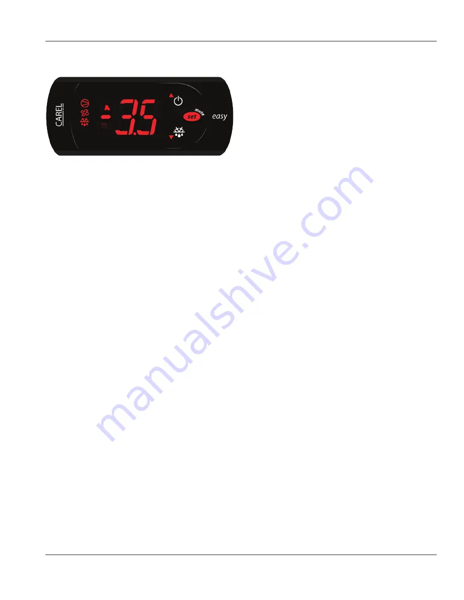
Electronic Temperature Control Location & Adjustment

Location

The Carel temperature control is mounted in a junction box 

on the back of the unit that includes the thermistors and 

power cord.

Start-up

At initial start-up or anytime power is disconnected and 

then reconnected to the unit, the control will start the unit 

in defrost.

Defrost

Defrost can be terminated and initiated by pressing 

the snowflake button. Display freezes the last cabinet 

tempurature recorded until defrost is completed and the 

cabinet reaches set point again.
The unit can be turned on and off by pressing the on/off 

button on the control.

Set Point Adjustment

To adjust the set-point temperature, press and hold the set 

button until the current set point appears and is blinking 

on the screen.  Press the down or up arrows to adjust to the 

desired temperature.  Press the set button again to save the 

temperature.

Factory set point:

407p Freezer  


-1.5°F

406p/4048 Cooler 

33°F

Error Codes
LED 

Flashes: This means there is a function that is being 

delayed by a timer/external signal or disabled by another 

process that is already going on.  For example, the 

compressor icon will flash if the cabinet temperature is 

above the cut-in temperature, but the control hasn’t met 

the minimum compressor off-time.

E0:

 Air probe error

E1: 

Coil probe error

LO: 

Low temperature alarm (-20°F for 90 minutes)

HI:

 High temperature alarm (+20°F for 90 minutes)

Ef: 

Unit operating on parameter error

Ed: 

Defrost ended on timeout rather than by temperature

Controls/Programming/Settings

R290 REFRIGERATORS

The control will initiate a defrost at start up. This defrost will 

continue up to 41°F or a minimum runtime of 1 minute/

maximum runtime of 75 minutes. The evaporator fans will 

run continually during the operation of the unit. There will 

be no drip time after the defrost. The compressor powers 

on immediately after reaching defrost termination temp. 
When the control calls for cooling, a minimum compressor 

on time is 2 minutes. Condensing unit/evaporator fans 

power on and the normal cooling cycle continues. 
Defrost will initiate after 6 hours of actual time (note: this 

is not running time). Display freezes the last cabinet temp 

recorded until defrost is completed and the cabinet reaches 

set point again.

Summary of Contents for Delfield 4000P Series

Page 1: ...d Maintenance Manual This manual is updated as new information and models are released Visit our website for the latest manual Note additional shelves shown above Part Number 9294045C 03 22 Original Document Caution Read this instruction before operating this equipment Fresh Solutions Fit For You ...

Page 2: ...wool or ceramic fibers crystalline silica and or carbon monoxide Inhalation of airborne particles of glasswool or ceramic fibers is known to the State of California to cause cancer Inhalation of carbon monoxide is known to the State of California to cause birth defects or other reproductive harm nWarning Do not use electrical appliances inside the food storage compartments of the appliance unless ...

Page 3: ...e Power Cord Chart 7 Refrigeration 8 Drain Connections 8 Caster Or Leg Installation 8 Leg Leveling 9 Caster and Leg Mounting Detail 9 Loosen Freezer Compressor Bolts 9 Section 3 Operation Controls Programming Settings 13 R290 Refrigerators 13 Freezers 14 Evaporator Fan Operation 14 Section 4 Maintenance Interior Cleaning 16 Preventing Blower Coil Corrosion 16 Exterior Cleaning 16 Drain 16 Cleaning...

Page 4: ...counter Refrigerator With Subtop And 3 75 Casters 406CA CE Undercounter Freezer Base With Stainless Steel Top 407P CE1 407P CE2 407P DHL CE1 407P DHL CE2 Undercounter Freezer Base With Stainless Steel Top 407 CE Undercounter Freezer With Subtop And 3 75 Casters 407CAP CE 407CA CE Serial Number Location The serial number on 400 series compact refrigerators and freezers is printed on the right side ...

Page 5: ... is intended for indoor use only Do not install or operate this equipment in outdoor areas Caution Do not position the air intake vent near steam or heat exhaust of another appliance The location selected for the equipment must meet the following criteria If any of these criteria are not met select another location Units are intended for indoor use only The location MUST be level stable and capabl...

Page 6: ...he vents clean and free of obstruction Legs or casters must be used and not removed Dimensions Model Length Depth Height 402P 27 69cm 28 5 72cm 39 5 100cm 403P 27 69cm 28 5 72cm 35 5 90cm 406P 27 69cm 28 5 72cm 35 5 90cm 406CAP 27 69cm 27 75 70cm 33 25 84cm 407P 27 69cm 28 5 72cm 35 5 90cm 407CAP 27 69cm 27 75 70cm 33 25 84cm ST4048P 48 122cm 28 5 72cm 39 5 100cm UC4048P 48 122cm 28 5 72cm 35 5 90...

Page 7: ...re start up GROUND FAULT CIRCUIT INTERRUPTER Ground Fault Circuit Interrupter GFCI GFI protection is a system that shuts down the electric circuit opens it when it senses an unexpected loss of power presumably to ground Welbilt does not recommend the use of GFCI GFI circuit protection to energize our equipment If code requires the use of a GFCI GFI then you must follow the local code The circuit m...

Page 8: ...or casters must be installed and the legs or casters must be screwed in completely to prevent bending When casters are installed the mass of this unit will allow it to move uncontrolled on an inclined surface These units must be tethered secured to comply with all applicable codes nWarning The unit must be installed in a stable condition with the front wheels locked Locking the front casters after...

Page 9: ... door remain closed CASTER AND LEG MOUNTING DETAIL A universal bolt hole pattern is provided on the bottom of the cabinet It will accommodate any leg or caster Simply line up the plate holes with the corresponding cabinet holes 3 40 86mm 2 82 72mm 1 75 44mm 2 14 54mm 0 94 24mm NOTE If hole pattern on caster leg matches the one above mount in middle set of holes 3 Caster 3234024 5 Caster 3234161 6 ...

Page 10: ...10 Part Number 9294045C 03 22 Installation Section 2 THIS PAGE INTENTIONALLY LEFT BLANK ...

Page 11: ...Part Number 9294045C 03 22 11 Section 2 Installation THIS PAGE INTENTIONALLY LEFT BLANK ...

Page 12: ...t nWarning The operator of this equipment is solely responsible for ensuring safe holding temperature levels for all food items Failure to do so could result in unsafe food products for customers nWarning Overloading shelves can damage equipment or cause bodily injury nWarning Damp or wet hands may stick to cold surfaces nWarning Do not block the supply and return air grills or the air space aroun...

Page 13: ...ion that is being delayed by a timer external signal or disabled by another process that is already going on For example the compressor icon will flash if the cabinet temperature is above the cut in temperature but the control hasn t met the minimum compressor off time E0 Air probe error E1 Coil probe error LO Low temperature alarm 20 F for 90 minutes HI High temperature alarm 20 F for 90 minutes ...

Page 14: ...box at the rear of the unit It is factory set at mid range to maintain about 3 F 18 C box temperature To adjust for colder temperatures press and hold the set button until the current set point appears and is blinking on the screen Press the down arrow to adjust to the desired temperature Press the set button to save the temperature To adjust for warmer temperatures press and hold the set button u...

Page 15: ...rning When cleaning interior and exterior of unit care should be taken to avoid the front power switch and the rear power cord Keep water and or cleaning solutions away from these parts nWarning Never use a high pressure water jet for cleaning or hose down or flood interior or exterior of units with water Do not use power cleaning equipment steel wool scrapers or wire brushes on stainless steel or...

Page 16: ...ch drain can become loose or disconnected during normal use If you notice water accumulation on the inside of the unit be sure the drain tube is connected to the evaporator drain pan If water is collecting underneath the unit make sure the end of the drain tube is in the condensate evaporator The leveling of the unit is important as the units are designed to drain properly when level Be sure all d...

Page 17: ...ostat is not set too cold Also check gasket condition Cabinet temperature is too high Thermostat set too high Set thermostat to lower temperature Poor air circulation in cabinet Re arrange product to allow proper air circulation Exterior thermometer is out of calibration Re calibrate thermometer Excessive amount of warm product placed in cabinet Allow adequate time for product to cool down Prolong...

Page 18: ...18 Part Number 9294045C 03 22 Troubleshooting Section 5 406P and 4048P Wiring Diagram ...

Page 19: ...Part Number 9294045C 03 22 19 Section 5 Troubleshooting 407P Wiring Diagram ...

Page 20: ...DELFIELD 980 SOUTH ISABELLA ROAD MOUNT PLEASANT MI 48858 800 733 8821 WWW DELFIELD COM 2019 Welbilt Inc except where explicitly stated otherwise All rights reserved Part Number 9294045C 03 22 ...

Reviews: