background image

Part Number: 9294045  07/17

Installation 

Section 2

Caster Or Leg Installation

 DANGER

Legs or casters must be installed and the legs or casters 

must be screwed in completely to prevent bending. 

When casters are installed the mass of this unit will 

allow it to move uncontrolled on an inclined surface. 

These units must be tethered/secured to comply with 

all applicable codes. 

n

Warning

The unit must be installed in a stable condition with 

the front wheels locked. Locking the front casters after 

installation is the owner’s and operator’s responsibility.

n

Warning

Use a jack to lift the refrigeration unit off the ground 

just far enough to remove the leg/caster. Place blocking 

underneath the unit. Do not work underneath a raised 

unit without proper blocking. Do not lift the unit more 

than necessary to remove the leg/caster. Lifting the unit 

too far can make the unit unstable.

,

Caution

All single-section units require that the sw ivel casters 

be mounted on the front and rigid casters be mounted 

on the rear.

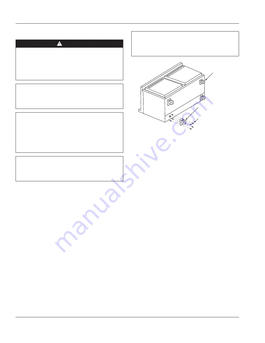
1.  Carefully place the unit on its back.
2.  Located at each caster mounting location are 4 Phillips 

head screws, for a total of 16 screws. Remove them.

3.  Place a locking plate caster or leg over one of the front 

holes, matching the 4 mounting holes to the pre-drilled 

holes in the underside of the unit. Insert 4 Phillips head 

screws and tighten. Repeat with the other locking front 

caster or leg.

4.  Repeat step 3 with the non-locking casters or legs in 

the rear of the unit.

5.  Carefully lift the unit upright.

,

Caution

After installing casters, the unit must stand upright for 

twenty-four (24) hours before being powered up to 

assure oil return to the compressor sump.

Plate Casters 

With Locks

Plate Casters 

Without Locks

Screws

LEG LEVELING
All four legs are adjustable. Adjust each leg until the unit is 

stable and level left to right. If necessary adjusting the front 

legs slightly higher than the rear by about 1/8” (3mm) will 

help the door remain closed.

Summary of Contents for Delfield 402P

Page 1: ...zers 400 4000 Series Original Instructions Installation Operation and Maintenance Manual This manual is updated as new information and models are released Visit our website for the latest manual 9294045 Part Number 9294045 07 17 ...

Page 2: ...this product could expose you to airborne particles of glasswool or ceramic fibers crystalline silica and or carbon monoxide Inhalation of airborne particles of glasswool or ceramic fibers is known to the State of California to cause cancer Inhalation of carbon monoxide is known to the State of California to cause birth defects or other reproductive harm nWarning Do not use electrical appliances o...

Page 3: ...tage Power Cord Chart 7 Refrigeration 7 Drain Connections 7 Caster Or Leg Installation 8 Leg Leveling 8 Caster and Leg Mounting Detail 9 Loosen Freezer Compressor Bolts 9 Section 3 Operation Controls Programming Settings 11 R404A Refrigerators 11 R290 Refrigerators 11 Freezers 12 Evaporator Fan Operation 12 Section 4 Maintenance Interior Cleaning 14 Preventing Blower Coil Corrosion 14 Exterior Cle...

Page 4: ...00 series compact refrigerators and freezers is printed on the right side of the interior back wall The serial tag on 4000 series compact refrigerators and freezers is located either on the left upper sidewall inside the cabinet or under the top nosing directly above the door when the door is in the closed position right hand door when there are two doors Always have the serial number of your unit...

Page 5: ...is intended for indoor use only Do not install or operate this equipment in outdoor areas Caution Do not position the air intake vent near steam or heat exhaust of another appliance The location selected for the equipment must meet the following criteria If any of these criteria are not met select another location Units are intended for indoor use only The location MUST be level stable and capable...

Page 6: ...f fire shock All minimum clearances must be maintained Do not obstruct vents or openings Back 3 00 76mm Top Sides 1 00 25mm Bottom 2 00 51mm Keep the vents clean and free of obstruction Legs or casters must be used and not removed Dimensions Model Length Depth Height 402P 27 69cm 28 5 72cm 39 5 100cm 406P 27 69cm 28 5 72cm 35 5 90cm 406CAP 27 69cm 27 75 70cm 33 25 84cm 407 27 69cm 28 5 72cm 35 5 9...

Page 7: ...ss of power presumably to ground Welbilt does not recommend the use of GFCI GFI circuit protection to energize our equipment If code requires the use of a GFCI GFI then you must follow the local code The circuit must be dedicated sized properly and there must be a panel GFCI GFI breaker We do not recommend the use of GFCI GFI outlets to energize our equipment as they are known for more intermitten...

Page 8: ...e Caution All single section units require that the sw ivel casters be mounted on the front and rigid casters be mounted on the rear 1 Carefully place the unit on its back 2 Located at each caster mounting location are 4 Phillips head screws for a total of 16 screws Remove them 3 Place a locking plate caster or leg over one of the front holes matching the 4 mounting holes to the pre drilled holes ...

Page 9: ...mount in outer set of holes 6 Leg 3234569 2 38 60mm 3 40 86mm 2 82 72mm 1 75 44mm 2 14 54mm 0 94 24mm NOTE If hole pattern on caster leg matches the one above mount in middle set of holes 3 Caster 3234024 5 Caster 3234161 6 Leg 3234791 2 14 54mm 0 94 24mm NOTE If hole pattern on caster leg matches the one above mount in inner set of holes 2 Caster 3234148 Loosen Freezer Compressor Bolts Semi herme...

Page 10: ...e the food storage compartment of this appliance nWarning The operator of this equipment is solely responsible for ensuring safe holding temperature levels for all food items Failure to do so could result in unsafe food products for customers nWarning Overloading shelves can damage equipment or cause bodily injury nWarning Damp or wet hands may stick to cold surfaces nWarning Do not block the supp...

Page 11: ...the doors closed the temperature of the cabinet should reach 36 F to 40 F 2 C to 4 C on refrigerators in about one hour The electronic temperature control constantly monitors box temperature and evaporator coil temperature to maintain consistent product temperatures Refrigerators periodically go into defrost to allow the accumulated frost on the evaporator to clear the compressor and condenser fan...

Page 12: ...re than one dial number and always allow eight hours for temperature stabilization before making any additional adjustments The control is located in the control box at the rear of the unit It is factory set at mid range to maintain about 3 F 18 C box temperature To adjust for colder temperatures turn the knob clockwise For warmer temperatures turn the knob counter clockwise Turn the knob fully co...

Page 13: ...ning When cleaning interior and exterior of unit care should be taken to avoid the front power switch and the rear power cord Keep water and or cleaning solutions away from these parts nWarning Never use a high pressure water jet for cleaning or hose down or flood interior or exterior of units with water Do not use power cleaning equipment steel wool scrapers or wire brushes on stainless steel or ...

Page 14: ...ch drain can become loose or disconnected during normal use If you notice water accumulation on the inside of the unit be sure the drain tube is connected to the evaporator drain pan If water is collecting underneath the unit make sure the end of the drain tube is in the condensate evaporator The leveling of the unit is important as the units are designed to drain properly when level Be sure all d...

Page 15: ...stat is not set too cold Also check gasket condition Cabinet temperature is too high Thermostat set too high Set thermostat to lower temperature Poor air circulation in cabinet Re arrange product to allow proper air circulation Exterior thermometer is out of calibration Re calibrate thermometer Excessive amount of warm product placed in cabinet Allow adequate time for product to cool down Prolonge...

Page 16: ...7 Welbilt provides the world s top chefs and premier chain operators or growing independents with industry leading equipment and solutions Our cutting edge designs and lean manufacturing tactics are powered by deep knowledge operator insights and culinary expertise All of our products are backed by KitchenCare our aftermarket repair and parts service CLEVELAND CONVOTHERM DELFIELD FITKITCHEN FRYMAS...

Reviews: