Part Number: 9294045 07/19
13
Section 2
Technical Information
7.2 - Chilling phases
Pressing the positive chilling button (2) or negative
chilling button (3) allows selection of a different chilling
mode. The number of LEDs lit (23) or (24) define the
“intensity” of chilling. The “Time” or “Temperature” chilling
mode will be set by pressing the button (5). Lighting up of
the corresponding LEDs on the sides will define the type
of chilling.
Each time the positive chilling button (2) is pressed the
display will show successively for 3 seconds one of the
following cycles:
LIGHT, SOFT, MEDIUM, FAST.
Each time the negative chilling button (3) is pressed the
display will show successively for 3 seconds one of the
following cycles:
LIGHT, SOFT, HARD, RUN.
7.3 - Selecting and starting the positive chilling cycle
When the button (2) is pressed for the first time, “SOFT”
mode will be selected, represented with lighting up of
two of the four LEDs (24); subsequent pressing takes to 3
and 4 LEDs lit and results in the “HARD” mode. Successive
pressing reduces from 4 to 1 the LEDs lit and so on.
“LIGHT” - 1 LED only on
In this condition, there will be a cell temperature set of
27F (-3C). This avoids the risk of ice formation during the
positive chilling phase and it will be used for loads which
can be damaged by excessively heavy treatment.
“SOFT” - 2 LEDs on (default)
In this condition, there will be a cell temperature set of 23F
(-5C). This set will allow quicker chilling for products that
in any case are fairly resistant to the freezing process.
“MEDIUM” - 3 LEDs on
In this condition, there will be an initial cell temperature
set of -4F (-20C); after the HARD time, this will be taked to
a cell temperature of 24F (-3C). This method accelerates
cooling in the presence of products that are resistant and
very hot initially.
“FAST” - 4 LEDs on
In this condition, there will be an initial cell temperature
set of -4F (-20C), after the HARD time, this will be taken to
a cell temperature of 23F (-5C). This method accelerates
cooling in the presence of products that are resistant and
very hot initially.
Once the MEDIUM or FAST cycles are started, to modify the
HARD phase duration simply press the button (2) that will
show on the display (19) the words “Hard” and will result
in flashing on the display (18) the value in minutes of the
HARD phase. With the +/- buttons it is possible to increase
or decrease the value and confirm with the button (2) or
wait 5 seconds (N.B. THE CHANGED VALUE ONLY APPLIES
TO THE CYCLE IN PROGRESS).
Once the cycle is selected, it is necessary to select the Time
or Temperature mode by pressing the button (5) until
coming on of the relevant LED.
At this point to start the cycle press the START/STOP
button (22).
In the even of Temperature chilling, it is possible to
change this chilling end value by pressing the button (2)
or (3) depending on the type of chilling in process. Having
pressed the button, the display (18) will appear the value
of the end chilling temperature set, which can be modified
within the envisaged range. Having pressed the button (2)
or (3) or after 5 seconds the changed value is saved.
7.4 - Selection and starting the Negative chilling cycle
Pressing the button (3) for the first time will select the
“HARD” mode, represented by coming on of three of the
four LEDs (23) present. Subsequent pressing will take to
4 the LEDs lit and will return into “RUN+HARD” mode.
Successive presses reduce from 4 to 1 the LEDs and so on.
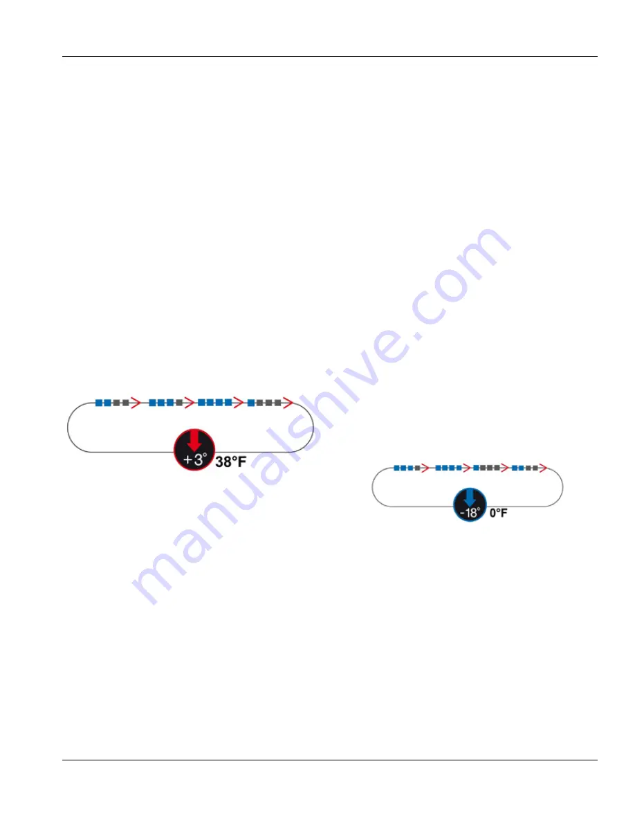
“LIGHT” - 1 LED only on
In this condition, there will be a cell temperature set of
23F (-5C); after the SOFT time defined by the parameter
(ts) this will move to a temperature of -22F (-30C). This
mode is for use on large pieces where it is important to
homogenise the chilling cycle.
“SOFT” - 2 LEDs on
In this condition, there will be a cell temperature set of
-4F (-20C); after the SOFT time defined by the parameter
(ts) this will move to a temperature of -22F (-30C). This
mode is for use on large pieces where it is important to
homogenise the chilling cycle.
In the case of SOFT or LIGHT temperature chilling, the
set change will be decided by the product temperature
detected according to the parameter (C2).
Summary of Contents for Delfield CV10E
Page 22: ...22 Part Number 9294045 07 19 Troubleshooting Section 4 T40 BLast Chiller Shock Freezer ...
Page 25: ...Part Number 9294045 07 19 25 Section 4 Troubleshooting T5 T14D Refrigeration System Schematic ...
Page 26: ...26 Part Number 9294045 07 19 Troubleshooting Section 4 T5 T14D Wiring Diagram ...
Page 31: ...Part Number 9294045 07 19 31 Section 4 Troubleshooting Controller Buttons ...
Page 41: ...Part Number 9294045 07 19 41 Section 4 Troubleshooting THIS PAGE INTENTIONALLY LEFT BLANK ...


