1-34
1.15.4 MIB (Manual Interface Board) Display Characters
A
– Auto Mode – Auto Filtration enabled.
E
– Drain or return valve is not in desired state. The display will alternate between
E
and the corresponding vat
number. Ensure the actuator is plugged in and an error does not exist.
– Three horizontal lines indicate the AIF temperature sensor did not detect that the vat was full during
auto filtration.
n
– Network Error - An “
n
” displays for 10 seconds if no communication is received from the cooking
controller within ten seconds after a power on or MIB reset.
P
– Pan Switch – Filter pan is improperly seated. Filtration is suspended.
r
– Reset Switch - Reset the vat closes all of the valves on the vat. If displayed for some time, there is probably
a problem with the board.
1 – 5
– Numbers which correspond to the vats with either an “L” indicating the left side of a split vat or “r”
indicating the right side of a split vat or a full vat. These numbers are displayed in manual mode.
1.15.5 Replacing the MIB Board
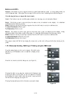
Disconnect the fryer from the electrical power supply. Remove the torx screw from the bottom of the MIB
cover, exposing the MIB board (see Figure 11). Remove the two cabinet screws at the top (see Figure 12).
Carefully hinge down the MIB board. Carefully remove the plugs on the rear of the board (see Figure 13).
Replace with a new MIB board and reverse steps to reassemble.
Once replaced, reconnect the power.
Readdress the MIB board following the instructions in the next section. Once replaced,
CYCLE POWER
TO ENTIRE FRYER SYSTEM.
See next section to reset control power. Check software version # and if
necessary update the software. If a software update is necessary, follow the instructions to update the
software in section 1.19.
Figure 11 Figure 12 Figure 13
Summary of Contents for Frymaster FilterQuick 2FQG30U
Page 8: ...1 3 ...
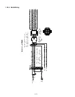
Page 41: ...1 36 1 16 2 Bulk Wiring ...
Page 56: ...1 51 1 18 6 Clogged Drain Failed Oil Sensor Error Flowchart ...
Page 57: ...1 52 1 18 7 Menu Trees 1 18 7 1 FilterQuick Controller Setup Menu Tree ...
Page 58: ...1 53 1 18 7 2 FilterQuick Filter and Info Mode Menu Tree ...
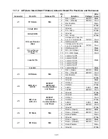
Page 62: ...1 57 1 20 Principal Wiring Connections ...
Page 63: ...1 58 1 21 Wiring Diagrams 1 21 1 Main FQG 230 430 120V CE Export ...
Page 64: ...1 59 1 21 2 Main FQG 230 430 Australia ...
Page 65: ...1 60 1 21 3 Main FQG 230 430 120V CE Export with Solid Shortening ...
Page 66: ...1 61 1 21 4 Main FQG 230 430 Australia with Solid Shortening ...
Page 67: ...1 62 1 21 5 Main FQG 330 530 120V CE Export ...
Page 68: ...1 63 1 21 6 Main FQG 330 530 Australia ...
Page 69: ...1 64 1 21 7 Main FQG 330 530 120V CE Export with Solid Shortening ...
Page 70: ...1 65 1 21 8 Main FQG 330 530 Australia with Solid Shortening ...
Page 71: ...1 66 1 21 9 Transformer Filter Box 430 530 ...
Page 73: ...1 68 1 22 2 FilterQuick FQG30 Series Simplified Wiring with Push Buttons ...
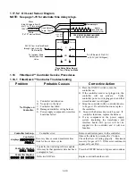
Page 74: ...1 69 1 22 3 FilterQuick FQG30 Series Data Network Flowchart ...
Page 76: ...1 71 1 24 Shortening Melting Unit Wiring Diagram ...
Page 77: ...1 72 1 25 Modular Basket Lift Wiring Diagram 100 120V 1 2 4 3 5 6 12 7 8050518E ...


