3 of 32
Part Number 020006830 04/23/2018
Subject: Installation Procedure Model WBK10X Water Booster Pump
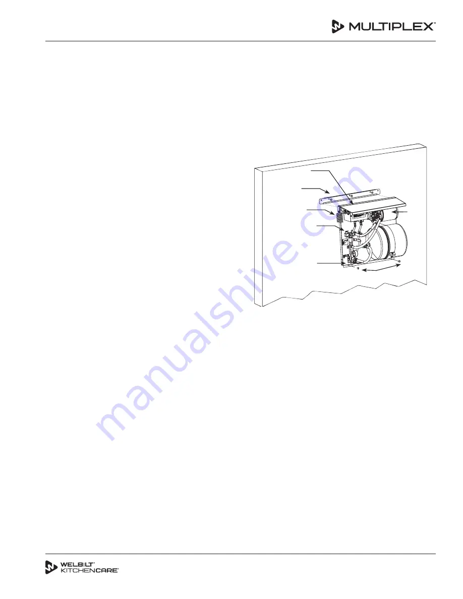
INSTALLING TO A WALL
1. Locate the six (6) 5/16" lag screws and the mounting
bracket.
2. Mount the J-channel to the wall, by using three (3)
screws (provided).
NOTE: Screws must be located in a stud. If mounting to
concrete wall, proper hardware (not provided) must be
used.
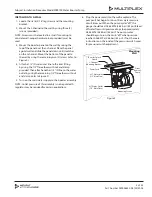
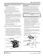
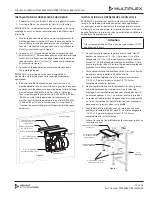
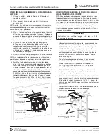
3. Mount the booster panel on the wall by raising the
top of the panel over the J-channel. Place the panel
against wall and slide the panel down until it catches
on the J-channel. Mount the bottom of the panel to
the wall by using the remaining two (2) screws (refer to
Figure 2).
4. Attach a 1/2" ID water inlet line to the inlet fitting
by using the 1/2" flare elbow with nut and clamp
provided. Then attach another 1/2" ID line to the water
outlet by using the remaining 1/2" flare elbow with nut
and clamp (refer to Figure 2).
5. Turn on the main water supply to the booster assembly.
NOTE: Outlet pressure of this assembly is not regulated. A
regulator may be required for certain applications.
6. Plug the power cord into the wall receptacle. The
pump will not begin to run until low water pressure
circuit times out. When the pump cycles “off”, the
gauge should read 0.586 MPa (5.86 bar) (85 psi). Bleed
off water flow until pressure drops to approximately
0.448 MPa (4.48 bar) (65 psi). The pump motor
should begin to run, then turn “off” when pressure
reaches 0.586 MPa (5.86 bar) (85 psi). If not, there are
instructions on the inside of the pressure switch cover
for pressure switch adjustment.
Booster Splash
Guard
J-Channel
Mounting Bracket
Power Cord
#27 Water Inlet
(1/2" Male Flare)
#27 Water Outlet
(1/2" Male Flare)
Mounting
Wall
Water
Booster
Pump
Mounting Screws
Figure 2


