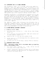
8.1 GENERAL NOTES
a. The Audiometer Board is a self-contained audiometric module.
If the board is changed, the headphones must be calibrated
to the board.
b. If during the calibration process, default data is loaded
then diagnostic mode D5 procedure must be performed (see
Section 4, Calibration of this manual).
C .
If the micro controller or audiometer board is changed then
default data,
and Diagnostic Mode D5 procedure must be
performed.
8.2 MICROCOMPUTER (U503)
The MC68HC11A1 is an 8 bit MCU with sophisticated on-chip
peripheral capabilities. In the GSI 17's application it operates
at a nominal 1 MHz bus speed. The HCMOS technology used combines
smaller size and higher speeds with the low.power and high noise
immunity of CMOS. On-chip memory includes 512 bytes of
electrically erasable programmable ROM (EEPROM) and 256 bytes of
random-access memory (RAM). The on-chip peripheral functions
include:
Eight channel analog to digital (A/D) converter with eight
bit resolution of which two channels (PE6 and PE7) are used
to monitor battery functions.
Free-running timer system that has three input capture
lines.
Two lines (PAO and PA1) are used to decode HL
direction and amount of change on an edge triggered basis.
The third input capture line (PA2) is used to detect left
vs. right output selection.
A real time interrupt function (XIRQ) which is used by the
Present Bar for immediate processing of a "Present" command.
Self-monitoring circuitry is included on-chip to protect
against system errors. This "computer operating properly"
(COP) watch dog system protects against software failures.
The internal 512 byte EEPROM contains data for the A/D converter
relative to the "LO BAT" (Low Battery) threshold and
"DEAD BAT"
or battery level below usable level threshold. Also stored in
the EEPROM are all calibration HL, SPL and attenuator data. This
data is stored with a triple redundancy technique. In this
method each calibration point per frequency is stored 3 times,
Summary of Contents for Grason-Stadler GSI 17 1717-9700
Page 1: ...Covers Welch Allyn AM232 Audiometer ...
Page 5: ......
Page 6: ......
Page 7: ......
Page 8: ......
Page 17: ...R 3 P io R 5 Figure 2 1 CONNECTORS CONTROLS INDICATORS 8 ...
Page 23: ......
Page 24: ......
Page 43: ......
Page 44: ......
Page 49: ......
Page 50: ......
Page 53: ......
Page 54: ......
Page 66: ......
Page 67: ......
Page 69: ......
Page 79: ......
Page 80: ......
Page 81: ......
Page 82: ......
Page 83: ......
Page 84: ......
Page 89: ......
Page 90: ......
Page 91: ......
Page 92: ......
Page 93: ......
Page 95: ...Figure 10 2 BATTERY POWER CONNECTION 88 ...
Page 98: ... v7044 0037 17 17 0406 Figure 10 3 NiCad BATTERY OPERATION 9 1 ...
Page 100: ......
Page 102: ......
Page 103: ......


