2–5
Operational Description
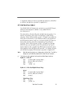
A complete description of bar code specifications for factors which affect
overall bar code quality are provided in Appendix B.9.
2.5 Interface Description
The SCANTEAM 6180 transmits bar code data in a serial ASCII format
(RS–232) and is designed to interface to any standard RS–232
asynchronous port.
The wand cable is offered with four (4) standard connector options. For
Option 1, the interface cable will be terminated in a 9 pin D female
connector. Power will be available on pin 9. If Option 2 is specified, the
cable will be terminated in a 9 pin D female connector with a pigtailed 5
pin DIN female connector for power. For Option 3§, RTS/CTS lines are
used and the interface cable will be terminated in a 9 pin D female
connector. Power will be available on pin 9. If Option 4§ is specified,
RTS/CTS lines are used and the cable will be terminated in a 9 pin D
female connector with a pigtailed 5 pin DIN female connector for power.
Pin assignments for each option are shown below. A complete wire color
code/function description of the interface is provided in Appendix B.3.
Note:
Data bits and stop bits are not configurable on the 6180. The 6180 is
always set up for data transmission at 7 data bits and 1 stop bit.
§
This feature is not supported in all wand models/software revisions.
Option 1 – 9 Pin D:
Pin 2
Transmit (Data from the Wand)
Pin 3
Receive (Data sent to Wand)
Pin 5
Ground
Pin 9
+5VDC + 5%
Option 2 – 9 Pin D w/Pigtail Power Plug:
9 Pin D
Pin 2
Transmit (Data from the Wand)
Pin 3
Receive (Data sent to Wand)
Pin 5
Ground
Pigtail Power Plug
Pin 1
Ground
Pin 3
+5VDC+ 5%
Summary of Contents for Scanteam 6180
Page 1: ...Serial Interface RS 232 Decoded Out Wand Technical Manual ...
Page 2: ......
Page 6: ...Limited Warranty ...
Page 12: ...vi Table of Contents ...
Page 46: ...4 22 Programming the Scanner ...
Page 52: ...5 6 Maintenance and Troubleshooting ...
Page 65: ... ...
Page 66: ......
Page 67: ......


