background image

4

SCANTEAM 6980 User’s Guide

Installation

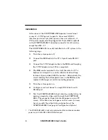
All versions of the SCANTEAM 6980 depend on an external
source of +5 VDC power to operate. Since most RSĆ232

interface ports don't provide a power source, an ex 5
VDC power supply must be plugged into the molded receptacle

in the SCANTEAM 6980's interface connector for all versions,
except the 6980-5

[

.

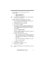
The SCANTEAM 6980 is easily installed into a PC system in the
following steps:
1) Turn the system power off.

2) Connect the MSR cable to the PC's 9 pin D male RSĆ232

port.

3) Connect the 5 VDC adaptor cable to the MSR and then plug

the 5 VDC adaptor into a 120 vac receptacle.

4) The MSR can be mounted to the wall, the side of a PC, a

keyboard, or simply to a counter with the hook and loop

fastener strips included with the product. Alternatively, the
screws holding the bottom plastic case on the MSR may be

replaced with longer screws for mounting purposes.

5) Turn the system power on.

6) Configure your host device to accept RSĆ232 data on its

RSĆ232 port.

7) Test the SCANTEAM 6980's host interface configuration by

passing a magnetic stripe card through the SCANTEAM
6980. The magnetic stripe data should appear on your PC

screen. If the data does not appear on the screen, you may
have to modify the output data configuration of the

SCANTEAM 6980 (see page 6, Configuration Options).

[

The SCANTEAM 6980–5 will only operate when the host device supplies
power on pin 9 of its DB-9 RS-232 interface port.

Summary of Contents for SCANTEAM 6980

Page 1: ...Please Note Finished document will be 5 5x8 5inches 3 hole punched folded and stapled RS 232 Interface Magnetic Stripe Card Reader...

Page 2: ...1998 Welch Allyn Inc All rights reserved...

Page 3: ...pas de bruits radioelectriques depassant les limites applicables aux appareils numeriques de la classe A prescrites dans le Reglement sur le brouillage radioelectrique edicte par le ministere des Com...

Page 4: ...ns 3 Configurations 3 Installation 4 Output Data Format 5 Configuration Options Dip Switch Controlled 6 Accessing the 6980 DIP Switch 7 Dip Switch Feature Selection 8 Configuration Options Download Co...

Page 5: ...not represent a commitment on the part of Welch Allyn Welch Allyn shall not be liable for technical or editorial errors or omissions contained herein nor for incidental or consequential damages result...

Page 6: ...1 SCANTEAM 6980 User s Guide 1 INTRODUCTION TO THE SCANTEAM 6980 Introduction...

Page 7: ...ectional Card Read Communications Parameters Changeable via DIP Switches Allows the MSR s communication settings to be changed in the field to meet the interface specifications of your host equipment...

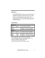
Page 8: ...3 SCANTEAM 6980 User s Guide Applications Configurations 1 1 1 1 0 0 1 1 0 0 1...

Page 9: ...4 The MSR can be mounted to the wall the side of a PC a keyboard or simply to a counter with the hook and loop fastener strips included with the product Alternatively the screws holding the bottom pl...

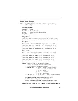
Page 10: ...TRACK 2 DATA ES CHECKSUM DLE STX SS TRACK 3 DATA ES CHECKSUM ETX Where STX START OF TEXT CHARACTER DLE DATA LINK ESCAPE CHARACTER ETX END OF TEXT CHARACTER SS Start sentinel Track 1 for ISO CA DMV AA...

Page 11: ...magnetic stripe to be transmitted or not transmitted to the host PC RS 232 Data Bit and Parity Selection This parameter allows you to change the MSR s serial RS 232 output parameters for character dat...

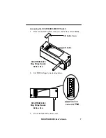
Page 12: ...7 SCANTEAM 6980 User s Guide Accessing the SCANTEAM 6980 DIP Switch...

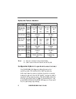
Page 13: ...ection Setting SW 1 Setting SW 3 Setting SW 4 Setting SW 6 Setting SW 7 Setting SW 8 SW 5 SW 2 Notes Asterisk Indicates Factory Default Setting Data Format includes one Start Bit and one Stop Bit Conf...

Page 14: ...executable file name at the command line The executable file is that shown on the SCANTEAM 6980 Programming Utility disk received with the MSR Example A MENU100A EXE The disk is in drive A and the exe...

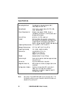
Page 15: ...4 in 10 0 cm Width 1 34 in 3 40 cm Height 1 67 in 4 24 cm Approximately 10 6 oz 300 g From card reader to computer approximately 5 feet 150 cm 9 pin D subminiature connector Current Draw 60 mA 5 VDC m...

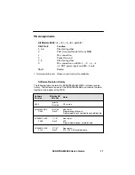
Page 16: ...gnments All Models 6980 1 2 3 4 and 5 DB 9 Pin Function Not standard product Please consult factory for availability Software Revision History 1 3 0 3 3 20 1 15 0 1 1 0 4 1 1 0 1 0 0 14 3 0 01 5 0 14...

Page 17: ...14 SCANTEAM 6980 User s Guide...

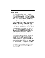
Page 18: ...air facility The responsibility to protect the reader from static damage is solely that of the user THE WARRANTIES SET FORTH HEREIN ARE IN LIEU OF ANY AND ALL OTHER WARRANTIES EXPRESSED OR IMPLIED INC...

Page 19: ...6980 UG Rev F S W M100B016 HEX F164...

Reviews: