background image

5

1.15 Electrical 

Power

1.151  Power Source Review
 

Review the power source and the motor rating to be sure they agree in voltage, phase and frequency.  On three-
phase applications the direction of rotation of the motor must be considered.  Make a momentary check rotation 
at the time of power installation and wiring.  Momentary backward rotation of the pump is not harmful.  Check the 
layout drawings for proper direction of rotation.  


CAUTION

Make certain the power settings on the pump match your power 

source before attempting to operate the pump

1.152 Overload 

Protection


Motor thermal overload protection is made available by the motor manufacturer as an aid to minimizing motor 
failure.  Overload protection is a standard feature on all single-phase 60Hz motors.  Single-phase motors will 
normally have automatic overload protection.  Motors of 1-1/2 horsepower or larger supplied with DUOSEAL 
pumps contain no overload protection.  Installations of such equipment must comply with local electrical codes 
which dictate appropriate starter and protection devices.  It is strongly suggested that you familiarize yourself 
with the protection supplied with your motor so that you may react accordingly in the event of an emergency.  
Automatic reset protection is designed to reset itself after a predetermined cooling period.  If the fault to the drive 
remains unaltered, the motor will cycle on and off until the fault is corrected.  The motor data plate will indicate the 
presence of thermal protection.

1.16 

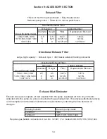
Vacuum Connections (See Accessory Section in back of this manual.)

1.161  Choice of Connections
 

The choice of connections and fi tting can have a very marked effect on the pumping speed at the vacuum 
chamber.  Any connection placed between the pump and the chamber creates an impedance to the fl ow of gas.  
This is particularly true at low pressures in the millitorr range where the gas fl ow is substantially molecular in 
character.  The gas fl ow is then dependent upon the kinetic activity of the molecules to bring it to the intake of the 
pump.

1.162  The Effects of Conductance
 

It has been shown that the conductance of a tube is proportional to the cube of its radius and inversely 
proportional to its length.  Therefore it is imperative that the connecting lines be as large in diameter and as short 
in length as practical.  For best results the diameter of the connecting tube should be at least as large as the 
diameter of the pump intake.  To avoid a large reduction in pumping speed at the vacuum chamber, it is clear that 
the conductance of the line must be considerably greater than the speed of the pump.

1.163 Metal 

Joints


If metal piping or tubing is used, it is preferable to solder or braze all of the connections.  Where threaded joints 
must be used, coat the threads with LocTite® Thread Sealant with PTFE, or Leak Lock and screw together tightly.  
Flanged connections with elastomer gaskets make excellent demountable joints.  Modular vacuum piping and 
fi ttings are now extensively used.

1.164 Rubber 

Tubing 

Joints


Where metal tubing is used between the system and the pump intake, joints can be make by butting the ends of 
the two sections together in a short section of vacuum hose.  Worm-screw band clamps are useful for securing 
the hose to the tubing.  Whatever the joint you choose to use, cleanliness should be of utmost importance.

1.165  Valves and Stopcocks
 

Metal valves or stopcocks may be used in the connecting line between the system and the pump to provide a 
means of isolating the pump from the system. To minimize the impedance of fl ow, the valve openings should be 
as large as possible.  Lubricate the rotating plug of the stopcock with a fi lm of vacuum grease suffi ciently thick 
enough to prevent seizure.

Summary of Contents for DUOSEAL 1405B-01

Page 1: ...essure will build up in the pump with the potential of the pump body bursting and causing possible injury to personnel in the area Part No 67 2061 R1 0 Printed in USA Welch Ilmvac 5621 W Howard Street...

Page 2: ...tions are found where failure to observe the instruction could result in damage to the equipment associated equipment and process These units conform to the SI International system of units of measure...

Page 3: ...10 3 30 Shaft Seal Replacement 10 3 40 Repairing Oil Leaks 11 3 50 Repairing Vacuum Leaks 11 3 60 Drive Problems 11 Section 04 Trouble Shooting Guide 4 10 Poor Vacuum Readings 12 4 20 Noisy Pump 12 4...

Page 4: ...to drive your particular pump at the recommended speed 1 13 Pump Location The pump should be located preferably in a clean and well ventilated area and adequate space should be provided wherever poss...

Page 5: ...creates an impedance to the flow of gas This is particularly true at low pressures in the millitorr range where the gas flow is substantially molecular in character The gas flow is then dependent upo...

Page 6: ...with the function and action of the pump which you have now required Remove the intake and exhaust port plugs and temporarily provide a stopper for the intake and a dust cap for the exhaust Review the...

Page 7: ...ir though the gas ballast valve to the mixture of vapor and gas being compressed the pressure required for delivery past the exhaust valve is reached with a considerably smaller reduction of the volum...

Page 8: ...rich in hydrogen and observing a sudden change in pressure on an electrical gauge The difference in calibration of these gauges for air and other gases will produce a distinct change in the pressure...

Page 9: ...system The required frequency of changes will vary with the particular system Experiences with the process will help you determine the normal period of operation before an oil change is required 3 103...

Page 10: ...rubber stopper Turn the pump on and run the pump for 10 minutes Close the gas ballast 8 Check the vacuum reading of the pump by connecting a thermocouple gauge tube to the pump s intake If the pump is...

Page 11: ...ng surfaces cleaned of any nicks 3 50 Repairing Vacuum Leaks 3 501 Surface Preparation Good Vacuum seals are an essential and important attribute of a good mechanical pump A good seal is dependent upo...

Page 12: ...t a forced oil flush 5 If noise level is still unsatisfactory consult with WELCH Technical Service at 847 676 8800 Ext 1 4 30 Excessive Oil Mist 1 Check oil level Maintain the level between the two li...

Page 13: ...cal Requirements 2 60Hz Electrical Requirements 3 1 Phase Replacement Parts Shaft Seal Lip Seal 1401E 01 Shaft Seal Mechanical Seal 1401E Air Filter Screen 41 0891 Intake Chamber Cover Gasket 41 1308...

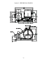
Page 14: ...Section 6 DIMENSIONAL DRAWING 14...

Page 15: ...nge High RPM direct drive vacuum pumps on the other hand experience a rapid fall off of pumping speed below 100 microns A comparison of the DuoSeal pumping speed curves shown below versus high RPM pum...

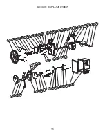
Page 16: ...Section 8 EXPLODED VIEW 16...

Page 17: ...CER 12 3 2 61 0000 WASHER STEEL 3 16 42 1 41 2160 BAFFLE ASSEMBLY 13 10 2 63 0193 WASHER LOCK 1 4 MEDIUM 43 1 41 2175 SETSCREW 1 4 20 x 2 25 LG 14 1 4 06 0754 1 1 ROTOR CLIP 44 6 41 2363 WASHER 5 16 I...

Page 18: ...101 Parts List for Model 61 8101 Item Qty P N Description 1 2 61 2229A Oil Window Glass 2 1 61 2278 Drain Valve 3 2 61 2370 Oil Window Cover 4 1 61 8833 Oil Case Machined 5 4 62 1014 Screw 8 32x3 8 Fl...

Page 19: ...ust Filter Use with pump model Dimension Catalog Number Diameter Height Filter Replacement Element 1392 1399 1400 1376 1380 1402 1400 1397 1374 2 5 5 5 2 5 6 25 9 1417L 1417G 1417H 01 1417L 1417G 1417...

Page 20: ...1922 Cat No 1 Element must be ordered with trap A2 Distance between ISO NW inlet and outlet connections Dry Ice Cold Traps Removable 3 quarter center well for dry ice alcohol slurry do not use acetone...

Page 21: ...best of our knowledge the above listed component is not hazardous according to OSHA 1910 1200 or one or more state right to know lists SECTION 3 HAZARDS IDENTIFICATION Major Route of Entry Skin conta...

Page 22: ...ection in Section 8 of this MSDS Inhalation Vaporization is not expected at ambient temperatures This material is not expected toques inhalation related disorders underanticipated conditions of use In...

Page 23: ...in Section 8 and Disposal Considerations in Section 13 of this MSDS Do not touch damaged containers or spilled material unless wearing appropriate protective equipment Slipping hazard do not walk thr...

Page 24: ...splashing or spraying conditions are present Protective clothing may include long sleeve outer garment apron or lab coat If significant contact occurs remove oil contaminated clothing as soon as possi...

Page 25: ...e low acute and sub acute toxicities in animals Effects from single and short term repeated exposures to high concentrations of mineral oil mists well above applicable workplace exposure levels includ...

Page 26: ...ry This product and or its components are listed on the Toxic Substance Control Act TSCA Inventory SARA 302 304 The Superfund Amendments and Reauthorization Act of 1986 SARA Title III requires Facilit...

Page 27: ...arks SECTION 16 OTHER INFORMATION Revision 4 Revision Date 11 11 03 ABBREVIATIONS AP Approximately EQ Equal GT Grater Than LT Less Than NA Not Applicable ND No Data NE Not Established ACGIH American C...

Page 28: ...or possession does not convey any rights to loan sell or otherwise disclose said information reproduction or use of said information for any purpose other than that in connection with said information...

Reviews: