background image

2.26

Dial Vacuum Gauge

A dial vacuum gauge is incorporated in the vacuum system.  The dial gauge is located in the top front section
of the system. The dial vacuum gauge is commonly used to indicate vacuum level when operating in the
rough vacuum range (0 to 29.9”Hg) Dial vacuum gauges give negative pressure - that is pressure below
atmospheric.  The reference point for the gauges is atmospheric pressure. Please keep in mind that atmo-
spheric pressure tends to vary from day to day.  As a result of this variability, a dial vacuum gauge will
indicate slightly different maximum vacuum readings from day to day.

2.27

Vacuum Level Regulation

Vacuum level regulation is accomplished with an adjustable bleed valve.  The adjustable bleed valve allows
close control of pressure in your apparatus.  Pressure may be set between roughly atmospheric pressure and
the maximum vacuum obtainable (9 torr, 29.6 in Hg).

2.28

Vacuum Connections

All Dry Vacuum Pumps come with intake and discharge hose barbs which accept 3/8” ID rubber pressure/
vacuum hose.  Hose clamps should be used to hold the hose in place.  Since all six models operate in the
viscous flow range, the small diameter of the hose will generate minimal conductance loss.  For best results,
Welch recommends the length of the tubing between the pump and the chamber be kept as small as possible.

2.29

Vacuum Gauges

Typical in the rough vacuum range, a dial vacuum gauge is used to measure pressure in mm, Hg or inches of
Hg.  The dial vacuum gauge gives negative pressure – that is pressure below atmospheric.  The reference
point for the vacuum gauge is atmospheric pressure.
Please keep in mind that atmospheric pressure tends to vary from day to day.  As a result of variability, the
dial vacuum gauge will indicate slightly different maximum vacuum readings from day to day.

2.30

Traps

2.31

The need for a Trap

The pumps will handle humid air.  All wetted aluminum parts are treated for corrosion protection from moisture.
All other wetted parts are stainless steel.  If there is a chance liquid may be drawn from the process under
evacuation, Welch recommends a liquid trap be placed between the process and the pump.  A simple liquid trap is
a filtering flask.
When a heavy load of water vapor is evolved from the vacuum process, a cold trap is recommended to help
prevent damage to the pump mechanism.  The cold trap, immersed in a suitable Dewar flask, is installed so
that the water vapor may come in contact with the surfaces of the trap and condense.  Commonly used
refrigerants are liquid nitrogen or dry ice and acetone or alcohol.  Dry ice provides sufficient cooling to freeze
out most heavy water vapor loads.  A variety of cold traps are available from Welch.
The symptom of a high water vapor load is if you have droplets coming out of the exhaust port.  If you see
droplets of water, Welch recommends you use a cold trap to capture the water before entering the pump or
dilute the water vapor stream by adding dry nitrogen to the gas flow.  Please call our customer service
department for additional information at (847) 676-8800 Ext. 1.

2.32

The care of a Trap

When using a cold trap the refrigerant should be maintained at a high level in the flask to keep the trap at a
uniformly low temperature.  If the trap is re-warmed it may allow re-evaporation of the condensate.  The
refrigerant add tube on the liquid nitrogen trap should not be obstructed as the refrigerant boil-off can produce
dangerously high pressures.  If the trap becomes saturated it should be disconnected from the system, drained
and cleaned.  An increase in pressure in the vacuum system will normally indicate that the trap has become
saturated.  To clean the trap, remove the trap from the system and allow the trap to warm up and rinse off the
condensate with a suitable solvent in a fume hood.  Thoroughly clean and dry the trap before reinstalling into
the system.

7

Summary of Contents for 2560

Page 1: ...r organic vapors or gases WARNING Be sure to properly identify intake and discharge before using pump See section 2 5 Welch Rietschle Thomas 7301 North Central Avenue Skokie IL 60077 Phone 847 676 8800 Fax 847 677 8606 E Mail welchvacuum thomasind com Part No 67 0974R2 8 Web Page www welchvacuum com Printed in the U S A ...

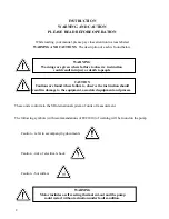
Page 2: ...ons are found where failure to observe the instruction should result in damage to the equipment associated equipment and process These units conform to the SI International system of units of measurement The following symbols with recommendations of IEC1010 of warning will be found on the pump Caution refer to accompanying documents Caution risk of electrical shock Caution hot surface WARNING Moto...

Page 3: ...n 6 Specifications Speed Curves Dimensional Drawings Parts List and Exploded View Application Information Warranty Welch Rietschle Thomas Read and understand the following information and instructions included with your Welch Dry Vacuum Pumps before using This information is for your safety and to prevent damage to the pumps 3 ...

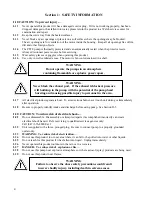
Page 4: ...tential of the pump head bursting and causing possible injury to personnel in the area I 17 All electrical products generate heat To avoid serious burns never touch unit during or immediately after operation I 18 Be sure to properly identify intake and discharge before using pump See Section II 5 I 20 CAUTION To reduce risk of electrical shock I 21 Do not disassemble Disassembly or attempted repai...

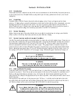
Page 5: ...rect or indirect moisture contact The pump should be located as closely to its system in order to utilize it most efficiently The pump is rated for indoor use only Maximum altitude 2000 meters Operating temperature range 5 C to 40 C Maximum relative humidity of 80 for temp up to 31 C decreasing to 50 at 40 C Rated for 10 of supply voltage Pollution Degree2 Installation Category II WARNING Don t op...

Page 6: ...ir or replacement of the cord or plug is necessary do not connect the grounding wire to either flat blade terminal The wire with insulation having an outer surface that is green with or without yellow stripes is the grounding wire Check with a qualified electrician or serviceman if the grounding instructions are not completely understood or if in doubt as to whether the product is properly grounde...

Page 7: ...d for a Trap The pumps will handle humid air All wetted aluminum parts are treated for corrosion protection from moisture All other wetted parts are stainless steel If there is a chance liquid may be drawn from the process under evacuation Welch recommends a liquid trap be placed between the process and the pump A simple liquid trap is a filtering flask When a heavy load of water vapor is evolved ...

Page 8: ...tection The importance of eliminating all leaks in a vacuum system is obvious The pump must remove this added volume of leaked gas to maintain the desired vacuum Leaks for these pumps can be located by slightly pressuring the system and painting the suspected area with a thick soap solution Escaping air will produce soap bubbles 3 14 Operating Pressure Range Models 2560 2561 2565 2580 2581 and 258...

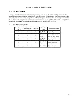
Page 9: ...apability This can be accomplished by blocking of the intake and reading the vacuum level on the gauge See Section 2 8 5 11 Troubleshooting Guide g n i p m u P r o o P d e e p S m u u c a V r o o P t i n U d u o L e l b i s s o P s e s u a C n o i t c A e v i t c e r r o C X X X d e g a m a D s e v l a V s e v l a v r e p p a l f e c a l p e R X X X n i s i r b e D s e v l a V d n a s i r b e d e ...

Page 10: ... o i s n e m i D l g n i p p i h S m c n i L m c n i W m c n i H 5 9 4 5 9 1 0 2 5 5 0 2 6 0 4 0 6 1 5 9 4 5 9 1 0 2 5 5 0 2 6 0 4 0 6 1 5 9 4 5 9 1 0 2 5 5 0 2 6 0 4 0 6 1 5 9 4 5 9 1 0 2 5 5 0 2 6 0 4 0 6 1 5 9 4 5 9 1 0 2 5 5 0 2 6 0 4 0 6 1 5 9 4 5 9 1 0 2 5 5 0 2 6 0 4 0 6 1 r e b m u N g o l a t a C h P 1 z H 0 6 V 5 1 1 r o f d e r i W g u l P V 5 1 1 n a c i r e m A N h t i W 1 0 B 0 6 5 2...

Page 11: ...6 11 Pumping Speed Curves 11 ...

Page 12: ...7 9 0 3 5 7 0 0 5 4 5 7 0 0 5 3 0 0 6 5 6 5 2 5 2 1 1 5 7 8 0 5 6 5 2 5 0 0 0 1 5 2 8 0 0 7 2 6 6 8 8 2 1 8 0 8 8 3 1 8 0 0 5 3 5 6 5 0 8 5 2 5 2 3 1 9 6 1 1 0 6 7 5 2 5 0 5 0 1 0 5 8 0 5 9 5 7 8 6 0 3 5 7 0 7 2 5 7 0 0 5 4 0 0 6 1 8 5 2 0 5 2 1 0 0 2 1 0 6 7 5 2 5 0 5 0 1 0 5 8 5 8 8 0 5 8 6 0 3 9 5 0 7 2 9 5 0 0 5 4 0 0 6 5 8 5 2 0 0 2 1 9 6 1 1 7 3 7 5 2 5 0 5 0 1 0 5 8 0 5 9 5 7 8 6 0 3 5 7 0 ...

Page 13: ... t i K e c i v r e S t e e F 4 0 K 0 0 5 2 1 1 0 K 5 6 5 2 y l b m e s s A d o R g n i t c e n n o C 1 2 2 6 2 7 8 1 6 w e r c S e l d n a H 2 2 3 4 1 3 3 1 6 e b u T r o t c e n n o C g n i R O 2 4 4 4 5 1 3 3 1 6 w e r c S d a e H 0 1 0 1 5 2 0 K 5 6 5 2 y l b m e s s A e t a l P e v l a V 2 2 6 6 1 3 3 1 6 e t a l P e v l a V g n i R O 2 2 2 7 7 1 3 3 1 6 r e d n i l y C g n i R O 2 2 2 8 C 2 1...

Page 14: ... F 4 0 K 0 0 5 2 1 3 0 6 3 1 6 p u C n o t s i P 2 2 2 4 0 6 3 1 6 w e r c S r e n i a t e R p u C 2 2 3 1 4 4 3 1 6 e v e e l S r e d n i l y C 2 2 4 2 5 0 1 2 6 t e k s a G g n i R O 2 2 2 5 7 0 6 3 1 6 w e r c S d a e H 6 6 6 8 8 2 0 6 6 e g a t S e k a t n I e v l a V e k a t n I 1 1 1 7 9 8 2 0 6 6 e v l a V t s u a h x E e k a t n I e g a t S t s u a h x E d n a e k a t n I 3 3 3 8 0 5 0 1 2...

Page 15: ... t i K e c i v r e S t e e F 4 0 K 0 0 5 2 1 1 0 K 5 6 5 2 y l b m e s s A d o R g n i t c e n n o C 1 2 2 6 2 7 8 1 6 w e r c S e l d n a H 2 2 3 4 1 3 3 1 6 e b u T r o t c e n n o C g n i R O 4 4 4 4 5 1 3 3 1 6 w e r c S d a e H 0 1 0 1 5 2 0 K 5 6 5 2 y l b m e s s A e t a l P e v l a V 2 2 6 6 1 3 3 1 6 e t a l P e v l a V g n i R O 2 2 2 7 7 1 3 3 1 6 r e d n i l y C g n i R O 2 2 2 8 C 2 1...

Page 16: ... l a e S 4 0 K 5 8 5 2 t i K e c i v r e S t e e F 4 0 K 0 0 5 2 1 1 0 K 5 8 5 2 y l b m e s s A d o R g n i t c e n n o C 2 2 2 3 7 3 0 1 6 e t a l P e v l a V g n i R O 2 2 2 3 4 7 3 0 1 6 e b u T r o t c e n n o C g n i R O 2 4 4 4 5 7 3 0 1 6 w e r c S d a e H 8 8 5 0 6 1 0 6 6 p u C n o i t c u S t e e F 4 4 6 2 0 K 5 8 5 2 y l b m e s s A e t a l P e v l a V 2 2 7 6 8 2 3 1 6 r e d n i l y C...

Page 17: ... 0 5 2 2 8 5 2 0 6 6 p u C n o t s i P 2 2 4 4 8 2 0 6 6 e v e e l S r e d n i l y C 2 2 5 6 8 2 3 1 6 r e d n i l y C g n i R O 2 2 6 0 9 2 0 6 6 e v l a V e k a t n I e g a t S e k a t n I 1 1 1 8 1 7 2 0 6 6 e v l a V t s u a h x E 2 2 2 0 1 4 2 6 3 2 6 e t a l P e v l a V g n i R O 2 2 2 3 1 6 7 2 0 6 6 e b u T r o t c e n n o C g n i R O 2 2 2 4 1 5 7 3 0 2 6 w e r c S d a e H 8 8 8 1 1 9 2 0...

Page 18: ... l a e S 4 0 K 5 8 5 2 t i K e c i v r e S t e e F 4 0 K 0 0 5 2 1 1 0 K 5 8 5 2 y l b m e s s A d o R g n i t c e n n o C 2 2 2 3 7 3 0 1 6 e t a l P e v l a V g n i R O 2 2 2 3 4 7 3 0 1 6 e b u T r o t c e n n o C g n i R O 4 4 4 4 5 7 3 0 1 6 w e r c S d a e H 8 8 5 0 6 1 0 6 6 p u C n o i t c u S t e e F 4 4 6 2 0 K 5 8 5 2 y l b m e s s A e t a l P e v l a V 2 2 7 6 8 2 3 1 6 r e d n i l y C...

Page 19: ...tions By turning clockwise the screw located on top of the orifice the vacuum level can be dropped to as low as 27 6 The deeper vacuum is particulary useful for removing sticky or viscous substance If you close off the orifice please keep in mind this will lead to restart problems if you are turning off then imediatly turning on the pump If you encounter a restart problem after closing the orifice...

Page 20: ...s of similar size This makes the 2561 and 2581 an economical oil free solution for replacing oil seal rotary vane pumps These pumps are therefore highly recommended for standard duty laboratory applications general vacuum work and where quick roughing of a chamber is needed The 2581 and 2561 pump Models are for use in standard duty applications This means that they are not recom mended for pumping...

Page 21: ...21 ...
Page 22: ... than replaced The warranty is effective for one year from the date of original purchase when 1 The warranty card has been completed and returned 2 The product is returned to the factory or other designated service centers freight prepaid 3 The product in our judgment is defective through no action or fault of the user If the product has become defective through misuse abuse alteration or ingestio...

Reviews: