47
MODULAR DRIVE SYSTEM TROUBLESHOOTING GUIDE
The Modular Drive System allows the user to mix and match components to custom build a machine for
an application. The resulting ability to replace and remove individual components while troubleshooting
significantly reduces the time and effort required to troubleshoot the system. The recommended trouble
-
shooting procedure is as follows:
1)
Verify that there are no loose electrical or mechanical connections.
2)
Verify that the welding power source is properly grounded and its ground clamp is attached to
the workpiece.
3)
Ensure the
High Frequency Warnings
in the front of this IPM are not being violated.
4)
When possible, swap out each component in the system one at a time with a known good
component. For example, replace the Control Module on a defective machine with the Control
Module from a working machine. Often, this will pinpoint the defective component quickly. If the
defective component is a Weaver Drive or a Master Drive, troubleshoot the drive to a circuit
board level using step 5 and/or 6 below.
5)
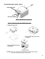
Remove all attached components. This includes the Remote Control Cable and Universal Limit
Kit. All attached components are removed to limit the number of components affecting the operation
and complexity of the system. Assemble a base system composed of a Control Module and
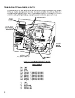
a Master Drive. Test the base system. If the base system does not work, troubleshoot the base
system to a circuit board level using the
Base System Test Procedure
. If possible, test the
Control Module by swapping it with a known good Module.
6)
If the system had a Weaver Drive, install it and retest the system. If the system does not work,
troubleshoot the system to a circuit board level using the Base System Test Procedure.
NOTE:
The weaver failure can result from a faulty Control Module, Master Drive or Weaver
Drive because they all interact. Use the Base System Test Procedure to find the faulty compo
-
nent.
7)
Some components require special attention when troubleshooting and have their own trouble
shooting section. These components are:
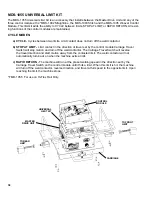
Universal Limit Kit (MDS-1055)
Perform any relevant troubleshooting section as required before proceeding to the base system
test procedure. The special troubleshooting sections are located after the Base System Test
Procedure.
8)
Finish installing the components one at a time. Test the system after each installation in order
to identify the problem components.

