52
TROUBLESHOOTING GUIDE, CONT’D.
PROBLEM
POSSIBLE CAUSE TEST BASE SYSTEM TEST PROCEDURE / REMEDY
Pendulum shaft
does not move.
Bad control module,
damaged power
cable, bad speed
board or bad
capacitor board.
8A
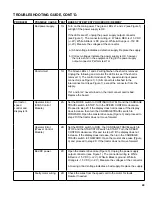
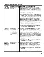
Set the weaver control module MODE SELECT switch to RUN
(no weave) and the START/STOP switch to START. Turn the
WEAVE SPEED to maximum. Move the STEERING CONTROL
knob clockwise and counter-clockwise. This should cause the
pendulum shaft to move back and forth.
a) If the pendulum output shaft moves, then proceed to step 8A.
b) Listen very closely to the Pendulum Gearbox to see if the motor
is turning. The gearbox is bad if the motor is turning but the
output shaft does not turn.
c) Remove the cable from between the electronics box and the
pendulum gearbox. Use a meter to verify the connections
through the cable. For example, verify pin A to pin A continuity,
pin B to pin B, etc.
d) Remove the pendulum weaver electronics box from the modular
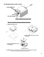
drive accessory port by removing 4 pan head screws (see
Figure 2). Open the master drive case (see Figure 3). Install
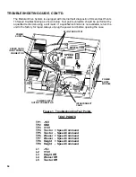
one voltmeter lead on TP6 and the other on TP7 (see Figure 1).
Turn on the unit, set the weaver control module MODE SELECT
switch to RUN (no weave) and the START/STOP switch to
START.
If reading is less than 2 V DC, adjust the STEERING pot on the
control module until the reading is greater than 2 V DC. Replace the
control module if the pot adjustment will not produce at least 2 V DC
on the voltmeter.
e) Reassemble the master drive case (see Figure 3). Open the
pendulum electronics box by removing the 4 pan head screws.
Install the back of the electronics box onto the master drive
unit. Locate the 2 pin connector on the speed board. Place the
voltmeter probes in the connector from the back. Set the control
module as follows.
1) Set the MODE switch to any mode except RUN (no weave)
2) Set the WEAVE SPEED to 3.
3) Set the WEAVE AMPLITUDE to maximum.
4) Set the RIGHT and LEFT DWELL to minimum.
5) Turn on the main power. Set the STOP/START switch to START
to enable weaver motion.
If the voltmeter reads 1.5 V DC or more, replace the gear motor box.
f) If the voltmeter reading is less than 1 V DC, unplug connector J1
from the speed board. Unplug connector JP1 from the capacitor
board and plug it into J1 on the speed board. Redo test 7D.

