ENGLISH
OM-235 816 Page 5
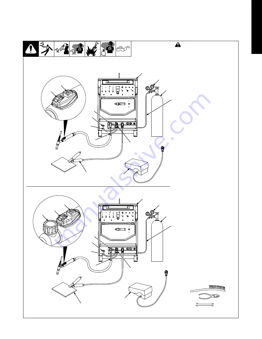
3-3. Connecting Torch
A. Connecting Torch With One-Piece Cable
!
Turn Off welding power source
power before installing torch.
Obtain the following hose:
1
Gas Hose With 5/8-18 Right-Hand
Fittings
2
Gas Cylinder
3
Regulator/Flowmeter
4
Welding Power Source
Connections:
5
International Style Connector
6
Gas Fitting
7
Short Gas Hose
8
Torch Power Cable
9
14-Pin Plug
Connect torch power cable to interna-
tional style connector (see Section 3-2).
Connect short gas hose to international
style connector.
Connect international style connector to
weld output terminal.
Connect remaining end of short gas
hose to gas fitting.
Connect 14-pin plug to matching recep-
tacle on power source.
10 Work Clamp
Connect work clamp to clean, paint-free
location on workpiece, close to weld.
Use wire brush to clean weld joint area.
Operation:
11 Contactor Control Switch
Use switch to turn torch on/off.
12 Amperage Control Dial
Turn dial to control amperage.
Operating Torch Gas Valve:
13 Torch Gas Valve
Valve controls gas preflow and postflow.
Open valve on torch just before welding.
Preflow is used to purge the immediate
weld area of atmosphere.
Postflow is required to cool tungsten and
weld, and to prevent contamination of
tungsten and weld. After welding, leave
valve open about 1 second for every 10
amperes of weld current. Close valve on
torch when postflow is finished.
14 Foot Control
Use of customer supplied foot control is
optional.
Tools Needed:
5/8, 7/8 in.
3
Torch Without Gas Valve
7
6
Torch With Gas Valve
.
If applicable, install high-frequency unit.
1
2
4
5
8
9
11
12
10
14
805 061-A
11
12
13
10
14
3
1
2
4
7
6
5
8
9
805 062-A


