background image

~

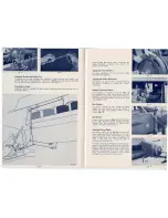
fig.36

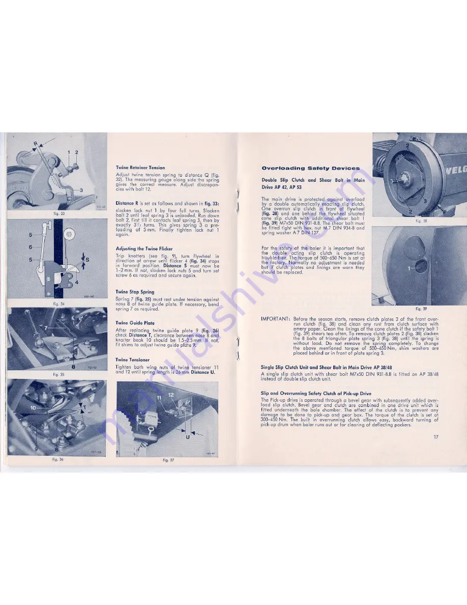
Twine Retainer Tension

Adjust twine tension spring to distance

Q (fig.

32).The

measuring gauge along side the spring

gi,ves the correct measure. Adjust discrepan-

eies with holt 12.

Distance R is set as fellows end shown in fig.33:

glocken lock nut 1 by tour full turns. Slacken

holt 2 until leGt spring 3 is unloaded. Run down
holt 2, first till it contacts leGt spring 3, then by
exactly 3'/2 turns. This gives spring 3 a pre-
loading

of 5 mm. Finally fighten lock nut 1

again.

Adjusting the Twine Flicker

Trip knotters

(see fig. 9), turn flywheel in

direction of arrow until flicker 4 (fig. 34) stops

in forward position. Distance S must now be
1-2 mm. If not, glocken lock nuts 5 end turn set

screw 6 as required end secure again.

Twine Stop Spring

Spring 7 (fig. 35) must rest under tension against

nase 8 of twine guide plate.

If

necessary, bend

spring 7 as required.

Twine Guide fiale

After replacing twine guide plate 9 (fig.

36)

check

DistanceT, clearance between nase 8 end

knotter heck 10 should be

1.5-2.5

mm. If not,

fit shims to adjust twine guide plate 9.

Twine Tensioner

Tighten both wing nuts of twine tensioner 11

end 12 until spring length is 26 mm Distance U.

fig. 37

j

~~

~

~

Overloading

Safety

Devices

Double Slip Clutch and

ShearBolt

in Main

Drive

AP 42, AP 53

The mein drive

is

protected

against overload

by d double automatically

reacting slip clutch.

. One

overrun

slip clutch in front

of flywheel

(fig.

38) end one behind ihe flywheel

situated

cone slip clutch with

additional

shear holt

1

(fig.

39) M7x50 DIN 931-8.8. The shear holt musr

.be fitted light with hex. nut M 7 DIN

934-8

end

spring washer A 7 DIN 127.

For the safety of the baler it is important

thaI

the

double

acting

slip

eluIeh

is

operating

trouble-free. The torque of

500-650

Nm is se,t at

the factory. Normally

no adjustment is needed

hut if clutch plates end linings are warn they
should be replaced.

IMPORTANT:

fig. 38

fig..39

Before the sepsen starts, remove clutch plates 2 of the front. over-

run clutch (fig. 38) end clean any fUgt from

clutch surface with

emery paper. Clean the linings of the cone eluIeh if the safety holt 1
(fig. 39) shears tao offen. T0 remove clutch plates 2 (fig. 38) glocken

the 8 halts of triangular

pfote spring 3 (fig. 38) until the spring is

without

load.

Do not remove the spring completely.

To chonge

the above

mentioned

torque

of

500,...650Nm, shim washers are

placed

behind or in front of plate spring 3.

Single Slip Clutch Unit and Shear Bolt in Main Drive AP

38/48

A single slip alutch unit with shear holt

M7x50

DIN

931-8.8is

fitted on AP 38/48

instead of double slip clutch unit.

Slip and Overrunning

Safety Clutch of Pick-up Drive

The Pick-up drive

is

operated through abevel

geer with subsequently added over-

load slip oIutch. Bevel geer end eluIeh are combined in one drive unit

which

is

fitted

underneath

the ba,le chamber. The effect of the clutch is to prevent any

damage to be düne to pick-up end geer box. The torque of the eluIeh is set at

300-450

Nm. The built in overrunning

cluleh pIlaws easy, backwardturning

of

pick-up drum when baler runs out or für clearing of deflecting packers.

17

Summary of Contents for AP 38

Page 1: ......

Page 2: ...h end Shear Bolt in Main Drive AP 42 AP 53 17 Single Slip Clutch Unit end Shear Bolt in Main Drive AP 48 17 Slip and Overrunning Safety Clutch of Pick up Drive 17 Safety Device for Packer end Cross fe...

Page 3: ...uble twine Tying material a sisalbaling twine 200 or 150 m kg 300 or 225 ft rlb 1 8 kg t 400 or 320 m kg 600 or 385 ft llb 0 9 kg t consumption approx 2 b plastic baling twine consumption approx 2 c w...

Page 4: ...on both stubs fig 3 slide pins must snap info position Secure safety chai n on to draw bar Fold joint prop 4 away to the rear as shown in fig 1 see arrow Clearance between pro end and traetor draw ba...

Page 5: ...e twine info both twine retainers PulI loops off both knotters remove twine ends from needle frame Bale Counter To have a control of the number of boles made the bole counter has to be turned to zero...

Page 6: ...should only be fitted when handling dry crops optional 2 or 4 pe Order number 1115 03 90 00 Drawbar Eye for 20 mm Pin Thi5 type of drawbar eye order number 1105 05 90 00 with pin part number 2101 05...

Page 7: ...old grease rims dust protection I Service of Gears Teeth of all spur end beye gears should be cleaned as necessary Road Wheels Check wheel nuts and Gaps and fixing bolts of wheel stub axles for light...

Page 8: ...e fig 9 open side cover 5 fig 25 remove locking bracket 7 from pinion 8 fig 21 Loosen olamping washer on pinion 8 end move pinion 8 sideways in direction of arrow until it is disengaged out off knotte...

Page 9: ...ead crank 4 fig 27 parallel to top edge of packer box 2 end block it there Turn flywheel in indicated direction until packer crank 1 hg 27 is in vertiwl position crank hanging downwards Now push hex s...

Page 10: ...one slip clutch with additional shear holt 1 fig 39 M7x50 DIN 931 8 8 The shear holt musr be fitted light with hex nut M 7 DIN 934 8 end spring washer A 7 DIN 127 For the safety of the baler it is imp...

Page 11: ...he pto end clear the feed fable by hand On no account attempt to remove the obstruction by reversing the PTO dri ve as this is Jiikely to band the leaf spring of the automatie clearing system out of s...

Page 12: ...e Check regular grease as necessary 14 Gear box 15 0 Shear lever shaft 160 Twine grip end knotter bearing see fig 16 17 Bearing plates on deflecting packer end cross feed AP42 53 only1x 3 1x 1x 2x 8x...

Page 13: ...ce I Attach baler I seefig 2 Incorrect C UPli 9 correctly land 3 I BQleVO ooded I Drive more slowly I I pick up lass I Main dri ve material 2 I dutch is slipping I Adjust clutch Torque is to smaH I se...

Page 14: ...holds twine far too slack 3 Knot not lied Knotter beak does not dose properly Spring h too slack twine retainer k does not hold twine during bole compaction Needle too far frorn knotter frame retaine...

Page 15: ...tor any length of time Regu larly check thai oll wirB guide rollers move easi ly grease as required Thoroughly lubri cate twister drive chain 11 fig 46 at frequent intervals Chain tension is operated...

Page 16: ...ossible to engage pinion in the above mentioned position remove guard out of twine box moye circlip 13 fig 23 on hex shaft about 300 mm to the left Block lead end flywheel Shift hex shaft 14 out of be...

Page 17: ...of slow rom speed I Remedy I I Cut off faulty ends re thread wire I I lmmerse coils in oi l allways store I them weil oiled I Clean end lubricate wire guide tubes I end rollers replace if necessary I...

Page 18: ...n dry place Stop barer before threading needles move safety lolch on tripping mechanism to position Aus All guards most be fitted in place and be in good condition Block road wheels with two chocks wh...

Reviews: