background image

Preparing

tor

Work

Balersare thoroughlytested and carefull

r

lubricated before leaving our werks and

are ready tor immediate service at fu,l capacity when observing the following

instruetions.

4

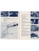
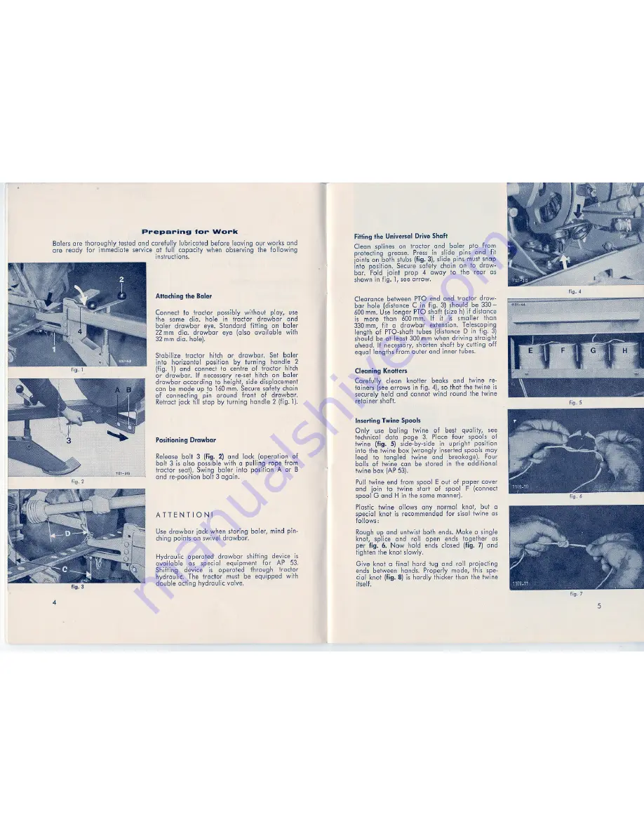
Attaching the Baler

Connect to traetor possibly without play, usa

the same dia. hole in traetor

drawbar

and

baler drawbar

are. Standard

fitting on baler

22 mm dia. drawbar

eye (also available

with

32 mm dia. hole).

Stabilize traetor

hitch or drawbar.

Set baler

info horizontal

position by turning handle 2

(fig. 1) and conneet to tantra of traetor hitch
or drawbar.

If necessary re-set hitch on baler

drawbar according to height, side displacement
can be made up to 160 mm. Secure safety chain

of conneeting pin around

front of drawbar.

Retraet jack till stop by turning handle 2 (fig. 1).

Positioning Drawbar

Release bell 3 (fig. 2) and lock (operation of
bell 3 is also possible with a puUing rope from

traetor seal). Swing baler info position A or B

and re-positi,on bell 3 again.

ATTENTION!

Usa drawbar jack when storing baler, mind pin-
thing po,ints on swivel drawbar.

Hydraul,ic operated

drawbar shifting device is

ava,i:lable as specia,! equipment

tor

AP 53.

ShiUing device

is opera ted through

traetor

hydraul,ic. The traetor

must be equipped with

double aeting hydraulic valve.

1

FiHingthe Universal Drive Shaft

Clean splines on traetor and baler pto from

proteeting grease. Press in slide pins and fit
joints on both stubs (fig. 3), slide pins must snap
info position. Secure safety chai,n on to draw-
bar. Fold joint prop 4 away to the rear as
shown in fig. 1, see arrow.

Clearance between pro

end and traetor draw-

bar hole (distance C in fig. 3) should be 330-

600 mm. Usa Ionger pro shaft (size h) if distance

is more thon 600 mm. If i.t is smaller thon

330 mm, fit a drawbar

extension. Telescoping

length of PTO-shaft tubes (distance D in fig. 3)

should be at least 300 mm when driving straight

ahead. If necessary, shorten shaft by cutting off
equallengths

from euter and inner tubes.

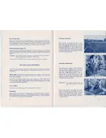
Cleaning KnoHers

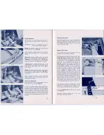
Carefully clean knotter beaks and twine re-

tainers (see arrows in fig. 4), so thaI the twine is

securely held and cannot wind round the twine

retainer shaft.

~

"

Inserting Twine Spools

Only usa baling

twine of best quality, see

technical data

page 3. Place tour spools of

twine (fig. 5) side-by-side in upright position

info the twine box (wrongly inserted spools may
lead to tangled

twi.ne and

breakage).

Four

balls of twine can be stored in the additional
twine box (AP 53).

Pull twine end from spool E out of paper cover

and

join to twine start of spool F (conneet

spool G and H in the same manner).

Plastoietwine allows any normal knot, but a

special knot is recommended tor si,sal twine as

fellows :

Rough up and untwist both ends. Make a single
knot, spließ and roll open ends together

as

per fig. 6. Now hold ends closed (fig. 7) and
fighten the knot slowly.

Give knot a final hard lug and roll proieeting
ends between hands. Properly made, this spe-

cial knot (fig. 8) is hardly thicker thon the twine

itself.

I-

fig.4

fig. 5

fig. 6

fig, 7

5

Summary of Contents for AP 38

Page 1: ......

Page 2: ...h end Shear Bolt in Main Drive AP 42 AP 53 17 Single Slip Clutch Unit end Shear Bolt in Main Drive AP 48 17 Slip and Overrunning Safety Clutch of Pick up Drive 17 Safety Device for Packer end Cross fe...

Page 3: ...uble twine Tying material a sisalbaling twine 200 or 150 m kg 300 or 225 ft rlb 1 8 kg t 400 or 320 m kg 600 or 385 ft llb 0 9 kg t consumption approx 2 b plastic baling twine consumption approx 2 c w...

Page 4: ...on both stubs fig 3 slide pins must snap info position Secure safety chai n on to draw bar Fold joint prop 4 away to the rear as shown in fig 1 see arrow Clearance between pro end and traetor draw ba...

Page 5: ...e twine info both twine retainers PulI loops off both knotters remove twine ends from needle frame Bale Counter To have a control of the number of boles made the bole counter has to be turned to zero...

Page 6: ...should only be fitted when handling dry crops optional 2 or 4 pe Order number 1115 03 90 00 Drawbar Eye for 20 mm Pin Thi5 type of drawbar eye order number 1105 05 90 00 with pin part number 2101 05...

Page 7: ...old grease rims dust protection I Service of Gears Teeth of all spur end beye gears should be cleaned as necessary Road Wheels Check wheel nuts and Gaps and fixing bolts of wheel stub axles for light...

Page 8: ...e fig 9 open side cover 5 fig 25 remove locking bracket 7 from pinion 8 fig 21 Loosen olamping washer on pinion 8 end move pinion 8 sideways in direction of arrow until it is disengaged out off knotte...

Page 9: ...ead crank 4 fig 27 parallel to top edge of packer box 2 end block it there Turn flywheel in indicated direction until packer crank 1 hg 27 is in vertiwl position crank hanging downwards Now push hex s...

Page 10: ...one slip clutch with additional shear holt 1 fig 39 M7x50 DIN 931 8 8 The shear holt musr be fitted light with hex nut M 7 DIN 934 8 end spring washer A 7 DIN 127 For the safety of the baler it is imp...

Page 11: ...he pto end clear the feed fable by hand On no account attempt to remove the obstruction by reversing the PTO dri ve as this is Jiikely to band the leaf spring of the automatie clearing system out of s...

Page 12: ...e Check regular grease as necessary 14 Gear box 15 0 Shear lever shaft 160 Twine grip end knotter bearing see fig 16 17 Bearing plates on deflecting packer end cross feed AP42 53 only1x 3 1x 1x 2x 8x...

Page 13: ...ce I Attach baler I seefig 2 Incorrect C UPli 9 correctly land 3 I BQleVO ooded I Drive more slowly I I pick up lass I Main dri ve material 2 I dutch is slipping I Adjust clutch Torque is to smaH I se...

Page 14: ...holds twine far too slack 3 Knot not lied Knotter beak does not dose properly Spring h too slack twine retainer k does not hold twine during bole compaction Needle too far frorn knotter frame retaine...

Page 15: ...tor any length of time Regu larly check thai oll wirB guide rollers move easi ly grease as required Thoroughly lubri cate twister drive chain 11 fig 46 at frequent intervals Chain tension is operated...

Page 16: ...ossible to engage pinion in the above mentioned position remove guard out of twine box moye circlip 13 fig 23 on hex shaft about 300 mm to the left Block lead end flywheel Shift hex shaft 14 out of be...

Page 17: ...of slow rom speed I Remedy I I Cut off faulty ends re thread wire I I lmmerse coils in oi l allways store I them weil oiled I Clean end lubricate wire guide tubes I end rollers replace if necessary I...

Page 18: ...n dry place Stop barer before threading needles move safety lolch on tripping mechanism to position Aus All guards most be fitted in place and be in good condition Block road wheels with two chocks wh...

Reviews: