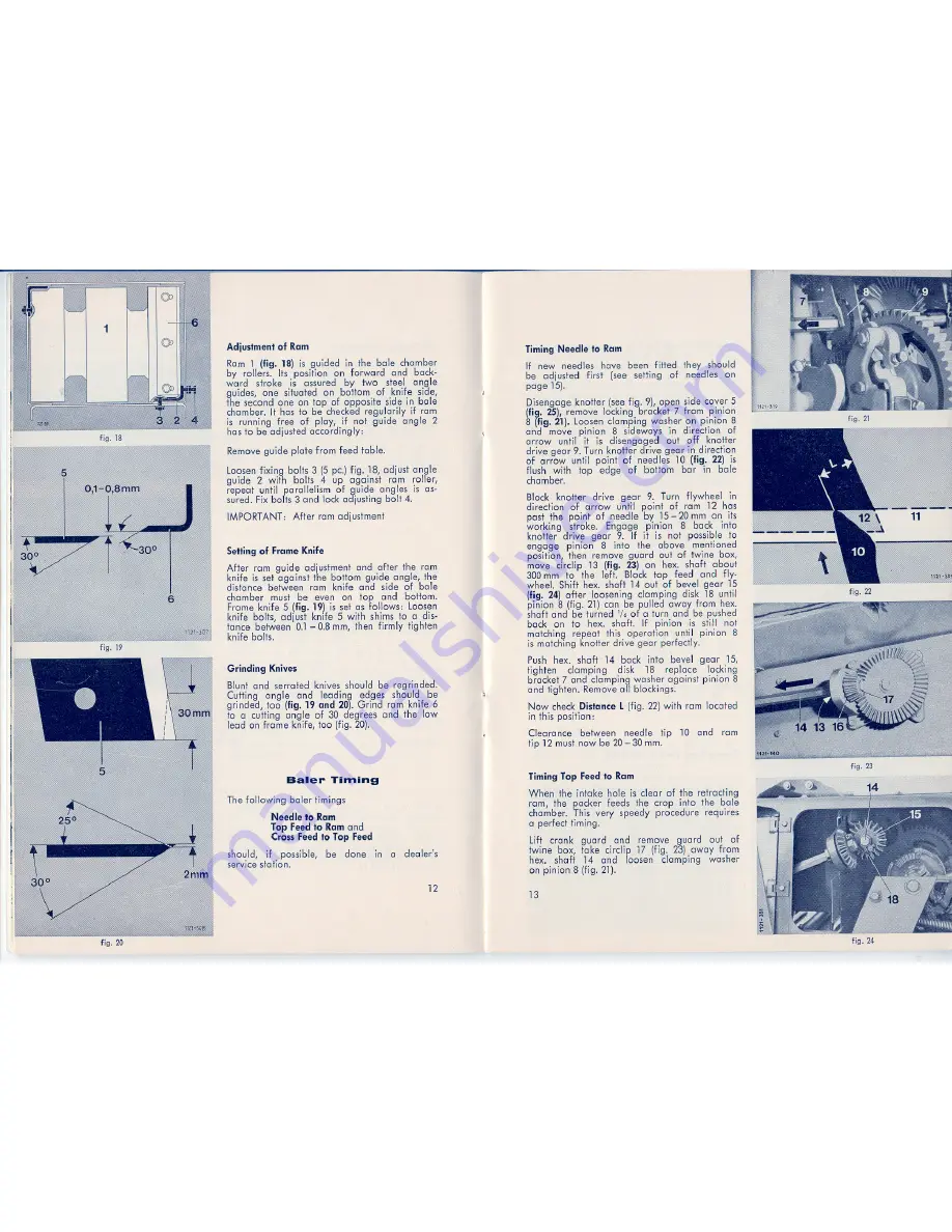
Adjuslmenl
of Ram
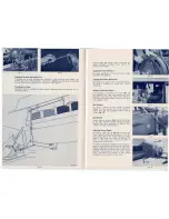
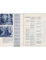
Ram 1 (fig.
18) is guided in the bole chamber
by rollers. Its position
on forward
end back-
ward
stroke
is assured by two
stee,1 angle
guides, one situated on bollom
of knife side,
the second one on top of opposite side in bole
chamber. It has 10 be checked regulari,ly if rom
is running free of pier,
if not guide angle 2
has to be adjusted accordingly:
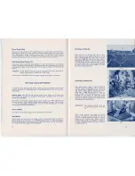
Remove gu'ide plate from feed fable.
Loosen fixing bolls 3 (5 pe.) fig. 18, adjust angle
guide
2 with
bolts 4 up against
rom roller,
repeat until parallelism
of guide angles is as-
sured. Fix bolts 3 end lock adjusting bolt 4.
IMPORTANT:
After rom adjustment
Setting of Frame Knife
After
rom guide adjustment end after the rom
knife is set against the bollom guide angle, the
distance between rom knife end side of bole
chamber
must be even on top
end
bollom.
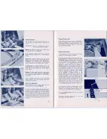
Frame kni,fe
5 (fig. 19) is set as fol,lows: Loosen
knife bolts, adjust knife 5 with shims to a dis-
tance between 0.1 - 0.8 mm, then firmly fighten
knife bolts.
Grinding
Knives
Blunt end serrated knives should be regrinded.
Culling
angle
end
leading
edges should
be
grinded, 100 (fig. 19 and 20). Grind rom knife 6
to a cutting angle of 30 degrees end the low
lead on frame knife, too (fig. 20).
Baler
Timing
The following
baler timings
Needle 10 Ram
Top Feed 10 Ram end
Cross
Feed 10 Top Feed
should,
if
possible,
be
done
in
servi,ce station.
a
dealer's
12
fig. 20
Timing Needle 10 Ram
If new needles have been fitted
they shou,ld
be adjusted
first
(see setting
of
needles on
page 15).
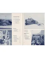
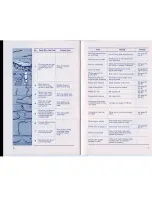
Disengage knotter (see fig. 9), open side cover 5
(fig. 25), remove locking bracket 7 from pinion
8 (fig.
21). Loosen olamping washer on pinion 8
end move pinion
8 sideways in direction
of
arrow
until
it is disengaged
out off
knotter
drive geer 9. Turn knotter drive geer in direction
of arrow until point of needles
10 (fig.
22) is
flush with
top
edge of
bollom
bar
in bole
chamber.
~
Block knoller
drive geer
9. Turn flywheel
in
direction
of arrow
until point of rom 12 has
post the point of needle by 15 - 20 mm on its
working
stroke.
Engage
pinion
8 back
info
knotter
drive geer 9. If it is not possible to
engage
pi nion
8 info
the above
mentioned
position, then remove guard out of Iwine box,
move
circlip .13 (fig.
23) on hex. shaft about
300 mm to the left. Block top feed
end fly-
wheel. Shift hex. shaft 14 out of bevel geer 15
(fig. 24) eHer loosening oIamping disk 18 unti,1
pinion 8 (fig. 21) can be pul.led away from hex.
shaft end be turned '/6 of a turn end be pushed
back on to hex. shaft. If pinion
,is sti,111
not
ma,tching repeat ,this operation
un~il pinion
8
is matching knoller dnive geer perfectly.
Push hex. shaft 14 back info bevel geer 15,
fighten
clamping
disk
18
replace
locking
bracket 7 end clamping washer aga,inst pinion 8
andtighten.
Remove oll blockings.
Now check
Dislance
L (fig. 22) with rom located
in this position:
Clearance
between
needle
tip
10 end
rom
tip 12 must now be 20
-
30 mm.
Timing Top Feed 10 Ram
When the intake
hole is dear of the retracting
rom, the packer feeds the crop info the bole
chamber. This very speedy procedure requires
a perfecttiming.
Lift
crank
guard
end
remove
guard
out
of
twi.ne
box, take circlip 17 (fig. 23) away from
hex. shaff
14 end
loosen
clamping
washer
on pinion 8 (fig. 21).
13
fig.22
fig. 23
fig.24
Summary of Contents for AP 38
Page 1: ......

